Electric anti-theft lock
An anti-theft lock and electric technology, which is applied in the field of anti-theft locks, can solve problems such as system disorder, battery theft, and unauthorized installation of equipment, and achieve the effects of high installability, reduced occupied space, and reduced occupied space
- Summary
- Abstract
- Description
- Claims
- Application Information
AI Technical Summary
Problems solved by technology
Method used
Image

Examples
Embodiment 1
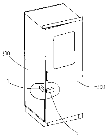
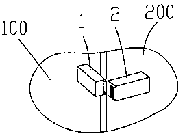
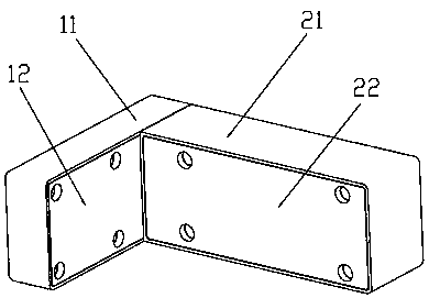
[0053] This embodiment discloses an electric anti-theft lock, comprising: a first lock case 1 and a second lock case 2, wherein, as Figure 4 As shown, the first lock housing 1 is composed of a housing 11 and a cover body. The interior of the housing 11 is divided into a cavity 112 and an installation cavity 111 by an extension plate, and an extension plate is formed by extending from the bottom of the housing 11 to the shell mouth. The extension plate Parallel to the wide side of the shell 11; as Figure 5 As shown, the inner cavity of the second lock housing 2 is equipped with a dead bolt 24 and a drive motor 23, the side wall of the second lock housing 2 is provided with a dead bolt 24 hole 212, part of the dead bolt 24 is provided with a rack, and the drive motor The output shaft of 23 is provided with a gear, and the drive motor 23, the gear, and the rack cooperate to make another part of the dead bolt 24 pass through the side wall and the cover of the second lock housing...
Embodiment 2
[0061] In order to prevent criminals from inserting a tool into the gap and moving the lock tongue 24 to unlock forcibly, on the basis of the disclosed scheme of embodiment 1, this embodiment also adopts the form of the installation gap between the first lock case 1 and the second lock case 2 in a folded line, Criminals cannot insert tools from the broken-line gap, so that the entire lock has an anti-theft function.
[0062] Such as Figure 6-Figure 10 As shown, the second lock case 2 extends toward the first lock case 1 to form a first protrusion 213 and a second protrusion 214, and the first protrusion 213, the second protrusion 214 and the hole 212 of the lock tongue 24 are located on the same side wall On; the extension length of the first protrusion 213 is greater than the extension length of the second protrusion 214; the first lock housing 1 is provided with a first embedding part for the first protrusion 213 to embed, and a second embedding part for the second protrusi...
Embodiment 3
[0070] This embodiment discloses the third anti-theft measure, that is, directly sends control instructions to the drive motor without designing a key, and then controls the unlocking and closing process. Considering the stability of the lock cylinder action of the electric anti-theft lock, such as Figure 11-14 As shown, the present embodiment provides the structure of the lock cylinder assembly.
[0071] Dead bolt 24, driving motor 23 and rack 243 are installed in the inner cavity of second lock housing 2, and dead bolt 24 is the knife-shaped structure of band handle, and dead bolt 24 comprises blade body portion 241 and handle portion 242; Rack 243 sets On the side wall of the knife handle portion 242; the drive motor 23 cooperates with the rack 243, so that part of the blade portion 241 stretches out from the side wall of the second lock housing 2 to realize locking; the drive motor 23 reversely rotates to make the blade portion 241 Retract the inner cavity of the second ...
PUM
| Property | Measurement | Unit |
|---|---|---|
| Wall thickness | aaaaa | aaaaa |
Abstract
Description
Claims
Application Information
 - R&D
- Intellectual Property
- Life Sciences
- Materials
- Tech Scout
- Unparalleled Data Quality
- Higher Quality Content
- 60% Fewer Hallucinations
Browse by: Latest US Patents, China's latest patents, Technical Efficacy Thesaurus, Application Domain, Technology Topic, Popular Technical Reports.
© 2025 PatSnap. All rights reserved.Legal|Privacy policy|Modern Slavery Act Transparency Statement|Sitemap|About US| Contact US: help@patsnap.com