Drying treatment device for spinning
A drying treatment and equipment technology, which is applied in the field of textile drying treatment equipment, can solve problems such as dust inclusions, large water vapor, and equipment cannot solve water vapor problems, and achieve the effect of preventing drainage from being blocked
- Summary
- Abstract
- Description
- Claims
- Application Information
AI Technical Summary
Problems solved by technology
Method used
Image

Examples
specific Embodiment approach 1
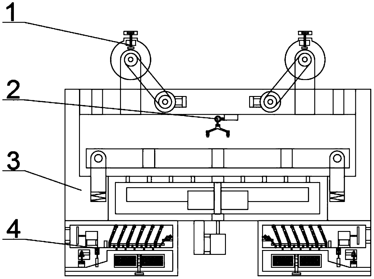
[0034] Combine below figure 1 , figure 2 , image 3 , Figure 4 , Figure 5 , Figure 6 , Figure 7 , Figure 8 , Figure 9 , Figure 10 , Figure 11 , Figure 12 , Figure 13 , Figure 14 , Figure 15 , Figure 16 , Figure 17 , Figure 18 Describe this embodiment. The present invention relates to a drying device, more specifically, a textile drying treatment equipment, including a cloth clamping mechanism 1, a shaking mechanism 2, a drying mechanism 3, and a dehumidification mechanism 4. The equipment can clamp Fabric, the equipment can dry the fabric, the equipment can shake the fabric, so that the fabric is heated evenly, the equipment can reduce the water vapor in the air, the device can filter the recovered water, and the device can prevent the silt from clogging the drainage.
[0035] The shaking mechanism 2 is located below the fabric clamping mechanism 1 , the fabric clamping mechanism 1 is connected to the drying mechanism 3 , and the dehumidifying m...
specific Embodiment approach 2
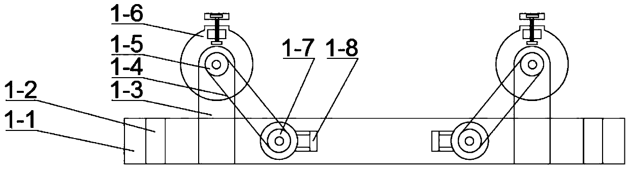
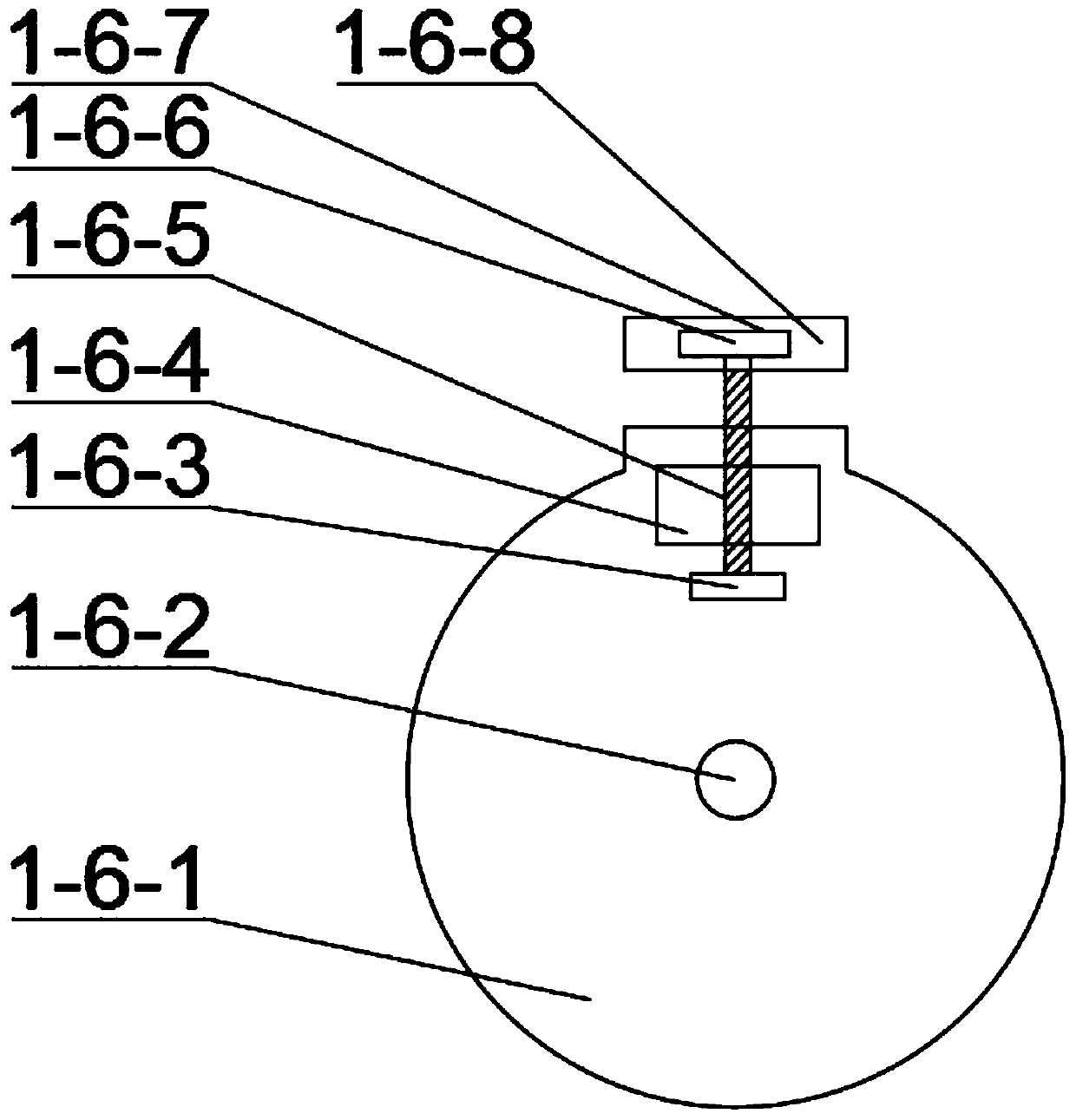
[0037] Combine below figure 1 , figure 2 , image 3 , Figure 4 , Figure 5 , Figure 6 , Figure 7 , Figure 8 , Figure 9 , Figure 10 , Figure 11 , Figure 12 , Figure 13 , Figure 14 , Figure 15 , Figure 16 , Figure 17 , Figure 18 Describe this embodiment, this embodiment will further explain Embodiment 1. The cloth clamping mechanism 1 includes an upper base body 1-1, a cloth passing groove 1-2, a support 1-3, a belt 1-4, and a pulley 1- 5. The clamping mechanism 1-6, the clamping pulley 1-7, the clamping motor 1-8, the cloth passing groove 1-2 is opened on the upper base 1-1, the support 1-3 is connected with the upper base 1-1, The connection mode between the belt 1-4 and the pulley 1-5 is a flexible connection, the pulley 1-5 is connected with the clamping mechanism 1-6, and the connection mode between the clamping mechanism 1-6 and the support 1-3 is a bearing connection, clamping The connection mode of the pulley 1-7 and the belt 1-4 is a flex...
specific Embodiment approach 3
[0039] Combine below figure 1 , figure 2 , image 3 , Figure 4 , Figure 5 , Figure 6 , Figure 7 , Figure 8 , Figure 9 , Figure 10 , Figure 11 , Figure 12 , Figure 13 , Figure 14 , Figure 15 , Figure 16 , Figure 17 , Figure 18 Describe this embodiment, this embodiment will further explain the first embodiment, the shaking mechanism 2 includes a strong magnet 2-1, a suction seat 2-2, a shaking spring 2-3, a hinge block 2-4, and a shaking frame 2 -5, slotting 2-6, shaking connecting rod 2-7, disc 2-8, disc motor 2-9, motor support 2-10, strong magnet 2-1 and suction seat 2-2. , the shaking spring 2-3 is welded between the suction seat 2-2 and the hinge block 2-4, the connection mode of the hinge block 2-4 and the shaking frame 2-5 is hinged, and the slot 2-6 is opened on the shaking frame 2 On the upper end face of -5, the lower end of the shaking connecting rod 2-7 is arranged in the slot 2-6, the shaking connecting rod 2-7 is hinged with the sha...
PUM
 Abstract
Description
Claims
Application Information
 - R&D
- Intellectual Property
- Life Sciences
- Materials
- Tech Scout
- Unparalleled Data Quality
- Higher Quality Content
- 60% Fewer Hallucinations
Browse by: Latest US Patents, China's latest patents, Technical Efficacy Thesaurus, Application Domain, Technology Topic, Popular Technical Reports.
© 2025 PatSnap. All rights reserved.Legal|Privacy policy|Modern Slavery Act Transparency Statement|Sitemap|About US| Contact US: help@patsnap.com