
Error estimation method and system for multi-sensor systems

A system error and error estimation technology, applied in the error estimation method and system field of multi-sensor systems, can solve problems such as large amount of calculation, performance degradation, poor real-time performance, etc., and achieve the effect of improving calculation efficiency

Active Publication Date: 2019-09-10
BEIJING INST OF ELECTRONICS SYST ENG
View PDF15 Cites 0 Cited by
  • Summary
  • Abstract
  • Description
  • Claims
  • Application Information

AI Technical Summary

Problems solved by technology

[0002] In the multi-radar network data processing, when the sensor platform is fixed and the sensor system error can be regarded as a fixed error when the regional climate, terrain and other factors are not considered, the existing system error estimation method can solve the problem under the premise of ensuring the estimation accuracy. The estimation algorithm based on the traditional generalized least squares (GLS) requires batch processing, a large amount of calculation, and poor real-time performance.
However, for a target whose rate is not too high, when the sensor continuously observes the target for multiple moments and performs error estimation based on the sequence of corresponding position measurement values, the system error and the measurement data are relatively close due to the close distance between the position points at adjacent moments. The coefficient matrix in the discretized relational model of the system will lead to slow convergence of the system error estimation problem, and even show ill-conditioned, severe degradation of performance

Method used


Image

  • Error estimation method and system for multi-sensor systems
  • Error estimation method and system for multi-sensor systems
  • Error estimation method and system for multi-sensor systems

Examples


Embodiment Construction

[0047] In order to illustrate the present invention more clearly, the present invention will be further described below in conjunction with preferred embodiments and accompanying drawings. Those skilled in the art should understand that the content specifically described below is illustrative rather than restrictive, and should not limit the protection scope of the present invention.

[0048] The purpose of the present invention is to provide an error estimation method for a multi-sensor system. Through the estimation and compensation of the system error, the accuracy of track association of the networked radar system is improved.

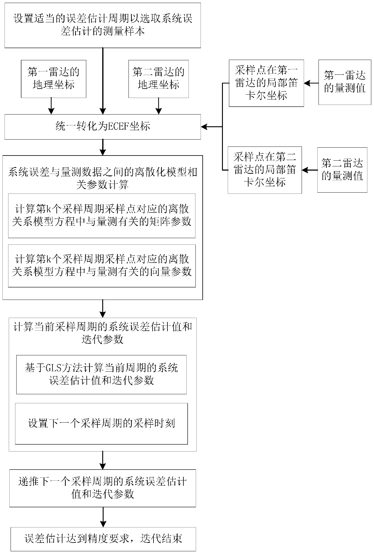
[0049] like figure 1 As shown, one embodiment of the present invention provides a method for error estimation of a multi-sensor system, comprising the following steps:

[0050] Collect the measurement data involved in the system error estimation according to the preset estimation cycle;

[0051]The system error estimate of the current preset est...


PUM


Abstract

The invention discloses an error estimation method and system for multi-sensor systems. A specific implementation manner of the method comprises the steps of acquiring measurement data participating in system error estimation according to a preset estimation period; obtaining a system error estimated value of the current preset estimation period through constructing a discrete model for a positionerror, obtained by a first radar and a second radar, of a same target at a same moment under a geographic coordinate system, a system error estimated value and a measurement data correlation quantity, and obtaining an iteration parameter of the current preset estimation period according to the measurement data correlation quantity; and obtaining a system error estimated value and an iteration parameter of the next preset estimation period according to the system error estimated value and the iteration parameter of the current preset estimation period and the measurement data of the next preset estimation period. According to the implementation manner, an interval sampling method is put forward, and an iterative correction method is utilized to calculate the system error estimated values,so that the calculation efficiency can be enhanced and the precision of the system error estimation and the fusion precision of an overall tracking system are ensured.

Description

technical field [0001] The invention relates to the technical field of system error estimation. More specifically, it relates to an error estimation method and system for a multi-sensor system. Background technique [0002] In the multi-radar network data processing, when the sensor platform is fixed and the sensor system error can be regarded as a fixed error when the regional climate, terrain and other factors are not considered, the existing system error estimation method can solve the problem under the premise of ensuring the estimation accuracy. The estimation algorithm based on the traditional generalized least squares (GLS) requires batch processing, which requires a large amount of calculation and poor real-time performance. However, for a target whose rate is not too high, when the sensor continuously observes the target for multiple moments and performs error estimation based on the sequence of corresponding position measurement values, the system error and the me...

Claims


Application Information

Patent Timeline
Patent Type & Authority Applications(China)
IPC IPC(8): G01S7/40
CPCG01S7/40
Inventor 张慧荣孙博文李喆刘娟娟徐大专
Owner BEIJING INST OF ELECTRONICS SYST ENG
Learn More