A method for calculating the thickness of filament wound composite shell head

A winding composite material and calculation method technology, which is applied in the field of calculation of the thickness of the head of the winding shell, can solve the problem that the actual winding line type cannot be considered, and achieve the effect of improving the calculation accuracy

Active Publication Date: 2022-04-26
陕西道博飞科新材料技术有限公司
View PDF1 Cites 0 Cited by
  • Summary
  • Abstract
  • Description
  • Claims
  • Application Information

AI Technical Summary

Problems solved by technology

[0009] In order to overcome the deficiency that the existing head thickness prediction method cannot consider the actual winding line type, the present invention proposes a head thickness calculation method based on the fiber winding process, which provides a method based on the winding track of the actual fiber bundle A New Method for Predicting the Thickness of Filament Wound Shell Head

Method used

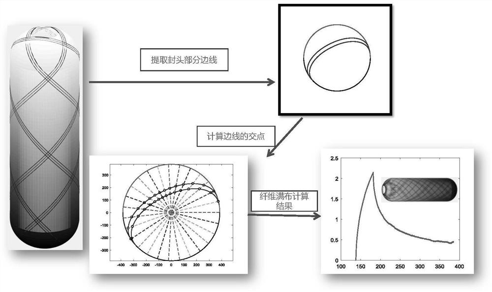
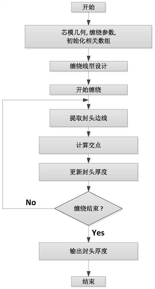
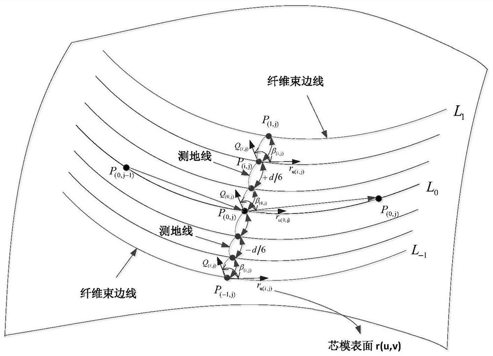

Image

  • A method for calculating the thickness of filament wound composite shell head
  • A method for calculating the thickness of filament wound composite shell head
  • A method for calculating the thickness of filament wound composite shell head

Examples


Embodiment Construction

[0059] Now in conjunction with embodiment, accompanying drawing, the present invention will be further described:

[0060] The present invention comprises following several parts:

[0061] 1. Obtain the winding parameters of the shell head section

[0062] During the filament winding process, the winding angle changes continuously along the axis of the mandrel. Obtaining an accurate winding angle distribution is the first step in calculating the fiber trajectory, and the calculation formula for the winding angle is as follows:

[0063]

[0064] In the formula, λ is the sliding line coefficient, α is the winding angle, r is the radius of the rotary section, r' and r″ are the first and second derivatives of the radius of the rotary section to the axis coordinate Z of the mandrel, respectively, and A is When λ=0, the equation degenerates into the Clairaut equation. When λ≠0, solving this equation can obtain the variation law of the non-geodesic winding angle along the axis ...


PUM


Abstract

The invention relates to a method for calculating the thickness of a shell head of a fiber-wound composite material. By solving the differential equations of the winding angle and the core mold rotation angle, the fiber trajectory corresponding to the actual winding line type is obtained. The geodesic offset method is used to calculate the fiber bundle edge of the head section. Considering that the radius of curvature of the head section is constantly changing, the fiber bundle is divided into multiple small segments, and then the geodesic offset angle is approximately considered to be unchanged on each small segment, so that the offset can be easily calculated on each tiny segment points until the calculation reaches the boundary. In order to facilitate the numerical calculation of the intersection point between the reference line and the fiber bundle sideline, the Cartesian coordinates of the fiber bundle sideline are transformed into polar coordinates, so that it is easy to calculate the intersection point between the reference line and the fiber bundle sideline by the method of linear difference. This method can be used to calculate the head thickness curve under the arbitrary winding linearity of the head of any shape, so that the influence of the winding linearity on the thickness of the head can be studied.

Description

technical field [0001] The invention relates to the field of shell design of fiber-wound composite materials, in particular to a method for calculating the thickness of the head of a wound shell. Background technique [0002] In the field of analysis and design of filament wound composite shells, the head part is generally the weak link. Accurate head thickness is very critical in the analysis. If the head thickness parameters are not known, it is impossible to model and analyze the head section of the shell, and it is impossible to calculate the accurate head stress and displacement parameters, which will lead to many problems. It is difficult to optimize the design of the winding shell and obtain the optimized parameters with the best performance. [0003] The existing head thickness calculation methods mainly include general single formula method, Gramoll and Namiki method and cubic spline fitting method. [0004] The general single formula method is based on the two as...

Claims


Application Information

Patent Timeline
Patent Type & Authority Patents(China)
IPC IPC(8): G06F30/20G06Q10/04B29C70/30B29C70/54G01B21/08
CPCG06Q10/04B29C70/30B29C70/54G01B21/08G06F30/20
Inventor 文立华郭凯特校金友
Owner 陕西道博飞科新材料技术有限公司
Why Eureka
Try Eureka