
Ball guide rail mold of battery capacitor sealing end cover

A technology for sealing end caps and battery capacitors, which is applied to battery caps/end caps, small-sized batteries/battery packs, capacitors, etc. It can solve the problems of not being able to be sealed and fixed, achieve good sealing and fixing, and ensure that the size is qualified The effect of improving the efficiency and improving the pull-off resistance

Pending Publication Date: 2019-09-10
合肥康特微科技有限公司
View PDF0 Cites 0 Cited by
  • Summary
  • Abstract
  • Description
  • Claims
  • Application Information

AI Technical Summary

Problems solved by technology

[0004] The purpose of the present invention is to provide a ball guide rail mold for sealing end caps of battery capacitors, which solves the disadvantage that traditional molds cannot press seal and fix all workpieces with inconsistent heights

Method used


Image

  • Ball guide rail mold of battery capacitor sealing end cover
  • Ball guide rail mold of battery capacitor sealing end cover
  • Ball guide rail mold of battery capacitor sealing end cover

Examples


Embodiment 1

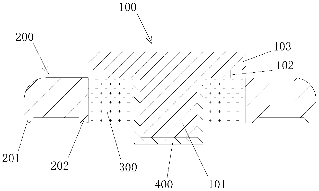
[0027] A ball guide rail mold for the sealed end cap of a battery capacitor, such as figure 1 As shown, the sealing end cap includes a substrate 200 and an electrode 100 , and the substrate 200 and the electrode 100 are assembled through a blank 300 and a metal sleeve 400 .

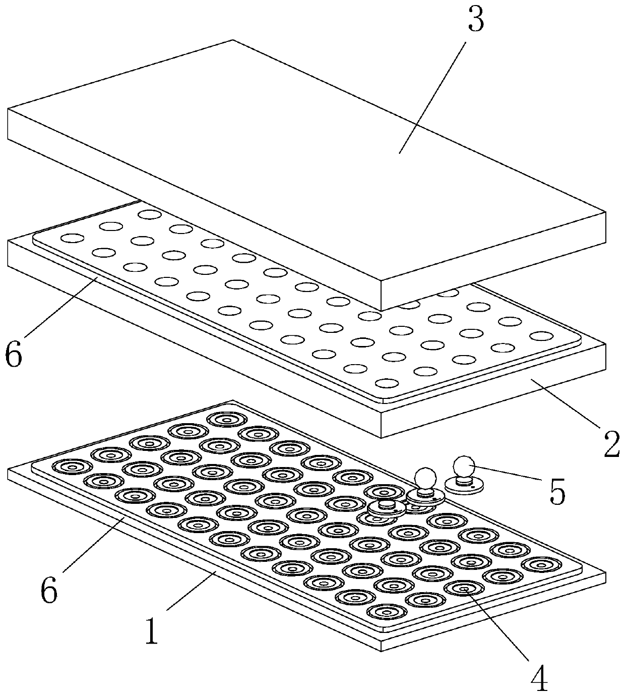
[0028] recombine Figure 2 to Figure 5 As shown, the ball guide rail mold is composed of the lower plate mold 1, the middle plate guide rail mold 2 and the upper cover plate mold 3. The inside of the ball guide rail mold is hollowed out to form a matrix-arranged workpiece placement area 4, and the bottom of the workpiece placement area 4 It is used to place the assembled sealing end cover workpiece, the shape of the bottom of the workpiece placement area 4 and the shape of the sealing end cover (for the specific assembly structure, refer to figure 1 and background technology introduction), so that the workpiece will not shake during the sintering and transportation process. And, each workpiece placement...

Embodiment 2

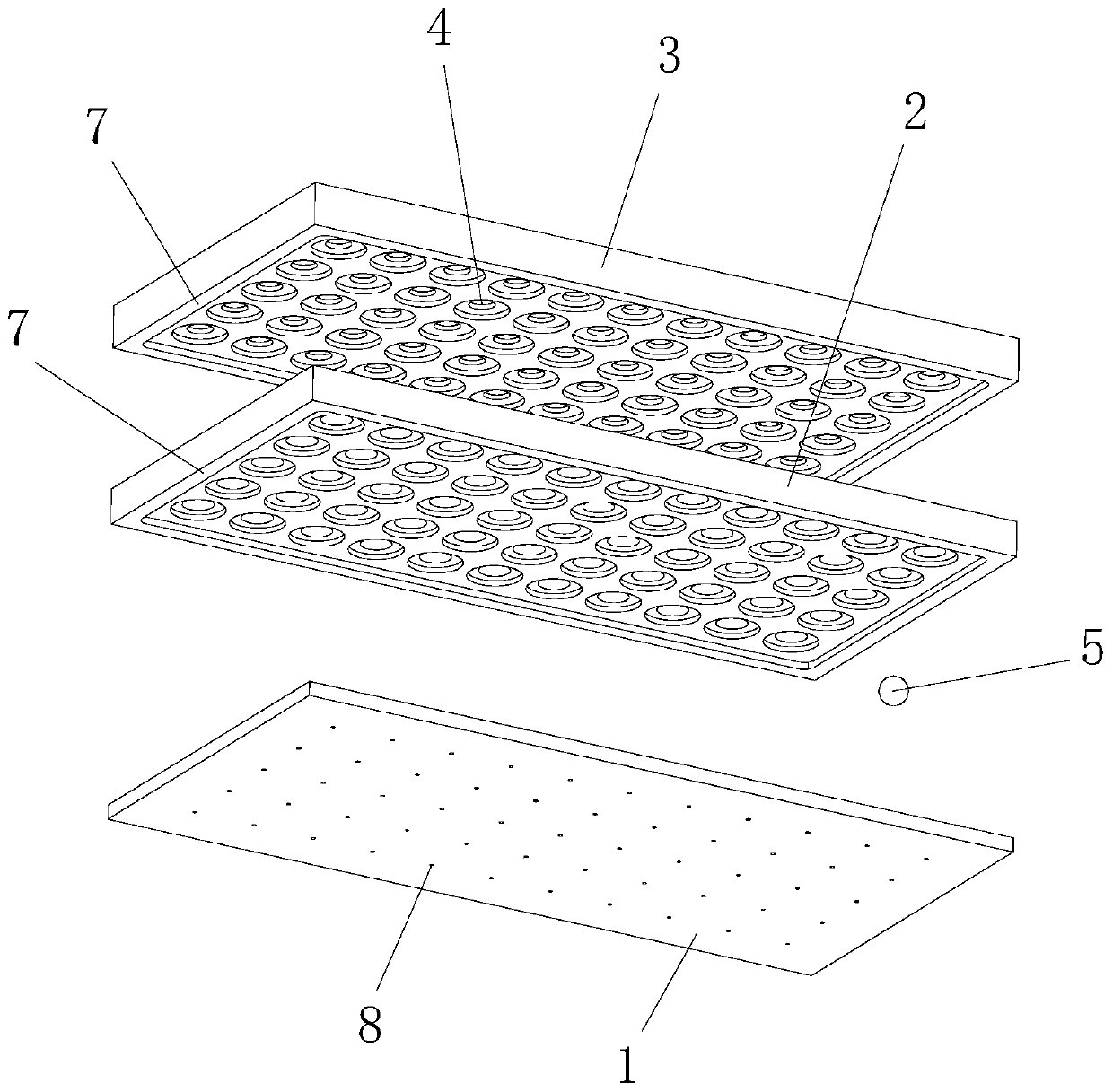
[0038] A guide post guide rail mold for sealing end caps, the main structure of which is the same as that of embodiment 1, the only difference is that the ball 5 is replaced by a guide post 9, and the bottom of the guide post 9 is made into a hemispherical structure. combine Figure 7 As shown, what is shown is that the workpiece is pressed and fixed by the self-weight of the guide post 9 .

[0039] Also, combine Figure 8 and Figure 9 As shown, the bottom of the above-mentioned guide post 9 is not necessarily a hemispherical structure, and other similar Figure 8 and Figure 9 Structure.

[0040] like Figure 10 As shown, the above-mentioned upper cover plate mold 3 can also be provided with vent holes 8 for further increasing the effect of ventilation and exhaust. The aperture of the vent hole 8 of the upper cover plate mold 3 is smaller than the diameter of the sphere 5 or the guide post 9 to prevent the sphere 5 or the guide post 9 from falling off from the vent hol...


PUM


Abstract

The invention discloses a ball guide rail mold of a battery capacitor sealing end cover. The sealing end cover comprises a substrate and an electrode, wherein the substrate and the electrode are assembled through a blank body and a metal sleeve; the ball guide rail mold is composed of a lower plate mold, a middle plate guide rail mold and an upper cover plate mold which are sequentially spliced, and workpiece placement areas which are in a matrix arrangement are formed in the ball guide rail mold in a hollowed-out mode; the bottom of each workpiece placement area is used for placing an assembled sealing end cover workpiece; and a ball body is further arranged in each workpiece placement area. The shape of the bottom of each workpiece placement area is the same as the shape of the corresponding sealing end cover, so that the workpiece does not shake in the sintering and transporting process, and the middle plate guide rail mold is additionally arranged, so that a ball (or a guide column) can be placed in each workpiece placement area; and through a self-weight extrusion action of the ball (or the guide column), each workpiece can obtain a relatively high pressure sealing and fixingeffect, the size percent of pass of the formed sealing end cover is guaranteed, and the performances such as anti-pull-off property, sealing performance and the like of the sealing end cover are improved.

Description

technical field [0001] The invention relates to the technical field of battery or capacitor production, in particular to a ball guide rail mold for a sealed end cap of a battery capacitor. Background technique [0002] At present, in the field of organic electrolyte battery and capacitor technology, the sealed end cover is used as the lead-out component of the battery and capacitor poles. While satisfying the lead-out electrodes, it is also necessary to ensure the insulation, strong corrosion resistance, pull-off resistance and sealing etc. The battery or capacitor sealing end cap is set at one end of the battery or capacitor case, such as figure 1 As shown, the sealing end cap mainly includes an electrode 100 and a substrate 200, wherein the electrode 100 is integrally formed by a lead-out electrode column 101, a crimping step 102 and a welding platform 103, and the substrate 200 is a ring structure, and the middle of the ring structure is used to lead out electrodes When...

Claims


Application Information

Patent Timeline
Patent Type & Authority Applications(China)
IPC IPC(8): H01G13/00H01M2/04H01M2/06H01M2/30H01M50/147H01M50/172H01M50/543
CPCH01G13/00H01M50/147H01M50/186H01M50/191H01M50/543Y02E60/10
Inventor 张肖康程秀云赵剑
Owner 合肥康特微科技有限公司
Features
  • Generate Ideas
  • Intellectual Property
  • Life Sciences
  • Materials
  • Tech Scout
  • Unparalleled Data Quality
  • Higher Quality Content
  • 60% Fewer Hallucinations
Learn More