Plasma processing system with faraday shielding device

A technology of Faraday shielding and plasma, applied in the direction of circuits, discharge tubes, electrical components, etc., can solve the problems of reduced wafer surface uniformity, reduced plasma processing system life cycle, and inability to clean the dielectric window, etc., to reduce the failure rate Effect

Inactive Publication Date: 2019-09-10
JIANGSU LEUVEN INSTR CO LTD
View PDF0 Cites 20 Cited by
  • Summary
  • Abstract
  • Description
  • Claims
  • Application Information

AI Technical Summary

Problems solved by technology

The Faraday shielding device is provided with an inlet nozzle that feeds process gas into the reaction chamber, but the Faraday shielding device in the prior art cannot clean the medium window around the inlet nozzle, resulting in local particle deposition. If the particle falls off And falling onto the wafer surface, it will cause the uniformity and defects of the wafer surface, and reduce the life cycle of the plasma processing system

Method used


Image

  • Plasma processing system with faraday shielding device
  • Plasma processing system with faraday shielding device
  • Plasma processing system with faraday shielding device

Examples


Embodiment 1

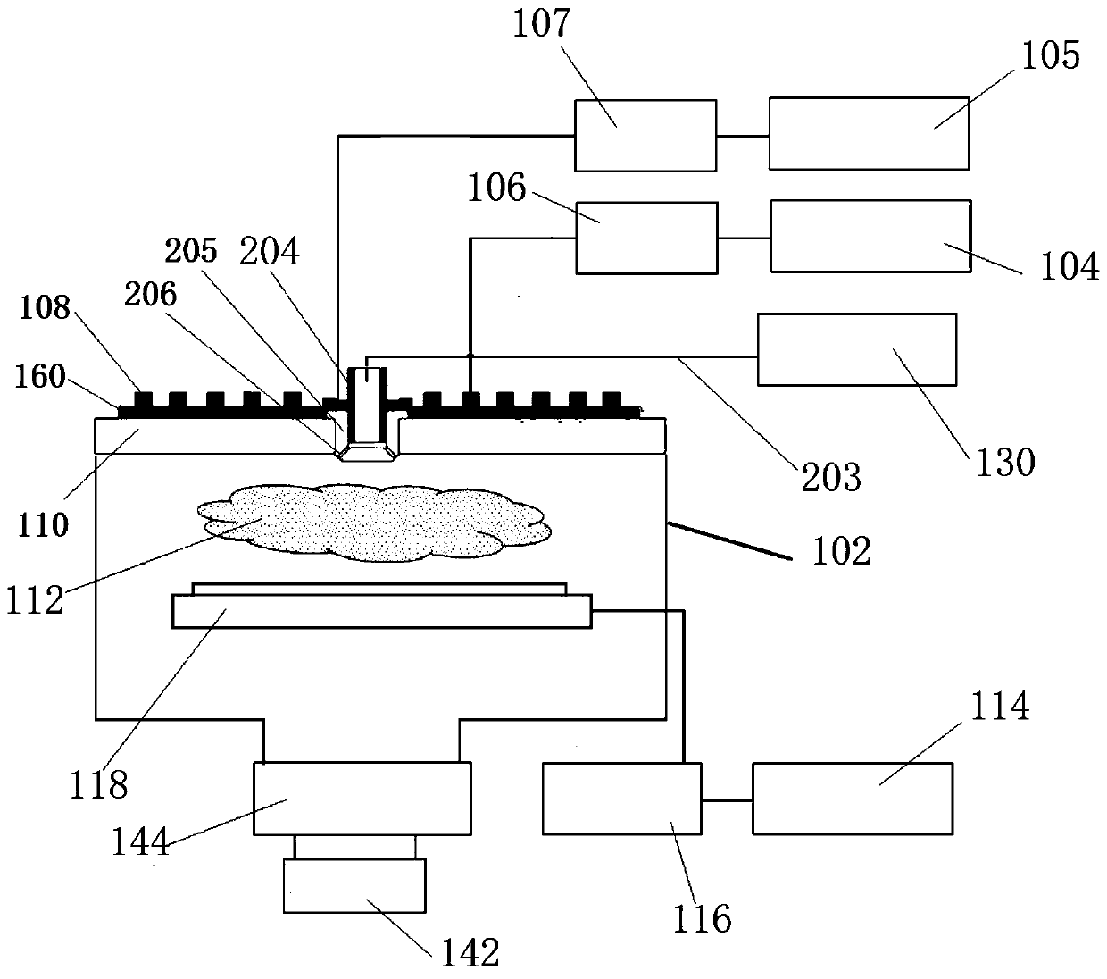
[0027] Embodiment 1, the air outlet port of the air intake nozzle 204 is connected to an extended air intake pipe 205 installed with insulating material; the extended air intake pipe 205 is provided with a number of first air intake holes 206; the extended air intake pipe 205 passes through The medium window 110 communicates with the reaction chamber 102 through the first inlet holes 206 ; the inner wall of the medium window 110 is located between the gas outlet port of the inlet nozzle 204 and the reaction chamber 102 . By extending the inlet pipe 205 , the gas outlet port of the inlet nozzle 204 can communicate with the reaction chamber 102 without protruding into the reaction chamber 102 . And the air outlet port of the air inlet nozzle 204 can be adjusted according to needs, and can be located between the inner wall and the outer wall of the medium window 110 , or can be located outside the outer wall of the medium window 110 . In addition, the extended air intake pipe 205...

Embodiment 2

[0029] Embodiment 2, the gas outlet port of the inlet nozzle 204 is embedded in the medium window 110, and the gas outlet port is located between the inner wall and the outer wall of the medium window 110; Several second air intake holes. Because the second embodiment needs to open holes on the dielectric window 110 , the processing cost is higher than that of the first embodiment, and it is not easy to maintain when the second air inlet is clogged or other faults occur.

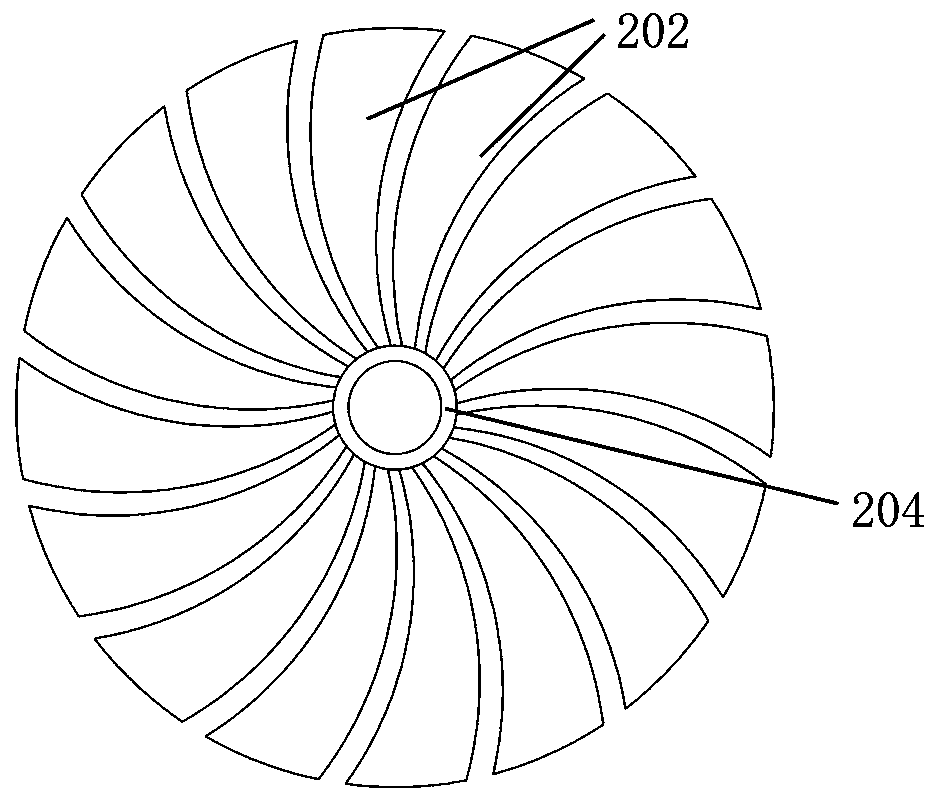
[0030] The Faraday shielding device 160 of the present invention includes a plurality of center-symmetric petal-shaped components 202 arranged at intervals; one end of the plurality of petal-shaped components 202 close to the center of symmetry is provided with a through hole. The air intake nozzle 204 passes through the through hole, and the inner circle of the through hole is electrically connected to the air intake nozzle 204. Specifically, the connection mode between the inner circle of the through hole ...


PUM


Abstract

The invention discloses a plasma processing system with a faraday shielding device. The plasma processing system comprises a reaction chamber, a faraday shielding device and an air inlet nozzle, wherein the faraday shielding device and the air inlet nozzle are positioned on the reaction chamber; the air inlet nozzle penetrates through the faraday shielding device to introduce process gas into thereaction chamber; the air inlet nozzle is made of a conductive material, and the air inlet nozzle is electrically connected with the faraday shielding device. According to the plasma processing systemin the invention, the air inlet nozzle of the conductive material is electrically connected with the faraday shielding device, when a cleaning process is carried out, cleaning process reaction gas ofan air inlet nozzle projection area is also electrically isolated, the cleaning process reaction gas forms a capacitive coupling plasma in the whole region below a dielectric window, and the dielectric window in the region surrounding the air inlet nozzle can be cleaned, so that all-directional cleaning of the inner wall of the dielectric window is realized, and the failure rate of the plasma processing system is reduced.

Description

technical field [0001] The invention belongs to the technical field of semiconductor etching, in particular to a plasma processing system with a Faraday shielding device. Background technique [0002] At present, non-volatile materials such as Pt, Ru, Ir, NiFe, and Au are mainly dry-etched by inductively coupled plasma (ICP). Inductively coupled plasma is typically generated by coils placed outside the plasma processing chamber adjacent to the dielectric window, and process gases within the chamber are ignited to form the plasma. During the dry etching process of non-volatile materials, due to the low vapor pressure of the reaction product, it is difficult to be pumped away by the vacuum pump, resulting in the deposition of the reaction product on the dielectric window and other inner walls of the plasma processing chamber. This not only creates particle contamination, but also causes the process to drift over time, making the process less repeatable. [0003] With the con...

Claims


Application Information

Patent Timeline
Patent Type & Authority Applications(China)
IPC IPC(8): H01J37/32
CPCH01J37/32091H01J37/32651H01J37/32862H01J37/3244H01J37/32119H01J37/32532H01J2237/026
Inventor 李雪冬刘小波胡冬冬刘海洋孙宏博车东晨许开东
Owner JIANGSU LEUVEN INSTR CO LTD
Why Eureka
Try Eureka