Three-phase Concentrated Bilateral Passive Rotor Transverse Flux Permanent Magnet Motor

A passive rotor, transverse magnetic flux technology, applied in the direction of magnetic circuit rotating parts, magnetic circuit shape/style/structure, magnetic circuit characterized by magnetic materials, etc., can solve the problem of low utilization rate of permanent magnets and complex rotor structure. And other issues

Active Publication Date: 2021-05-11
NANJING UNIV OF AERONAUTICS & ASTRONAUTICS
View PDF22 Cites 0 Cited by
  • Summary
  • Abstract
  • Description
  • Claims
  • Application Information

AI Technical Summary

Problems solved by technology

[0013] The technical problem to be solved by the present invention is to provide a three-phase magnetism-gathering double-sided passive rotor transverse flux permanent magnet motor, which realizes magnetism gathering from the permanent magnet to the stator core, and the double-sided rotor structure can make full use of the magnetic field generated by the permanent magnet, which solves the current problem. There are technical problems of low utilization rate of permanent magnets and complex rotor structure of transverse flux permanent magnet motors

Method used


Image

  • Three-phase Concentrated Bilateral Passive Rotor Transverse Flux Permanent Magnet Motor
  • Three-phase Concentrated Bilateral Passive Rotor Transverse Flux Permanent Magnet Motor
  • Three-phase Concentrated Bilateral Passive Rotor Transverse Flux Permanent Magnet Motor

Examples


Embodiment Construction

[0038] Embodiments of the present invention are described in detail below, examples of which are shown in the drawings, wherein the same or similar reference numerals denote the same or similar elements or elements having the same or similar functions throughout. The embodiments described below by referring to the figures are exemplary only for explaining the present invention and should not be construed as limiting the present invention.

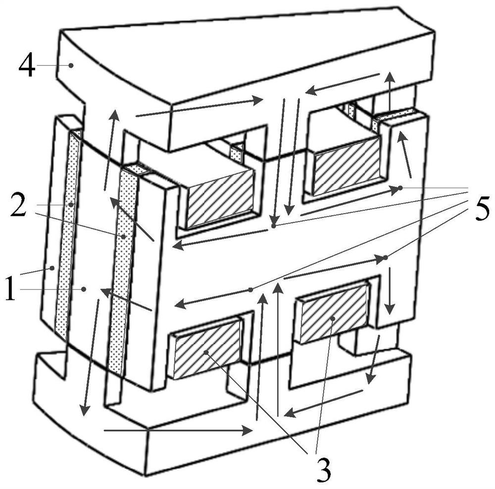
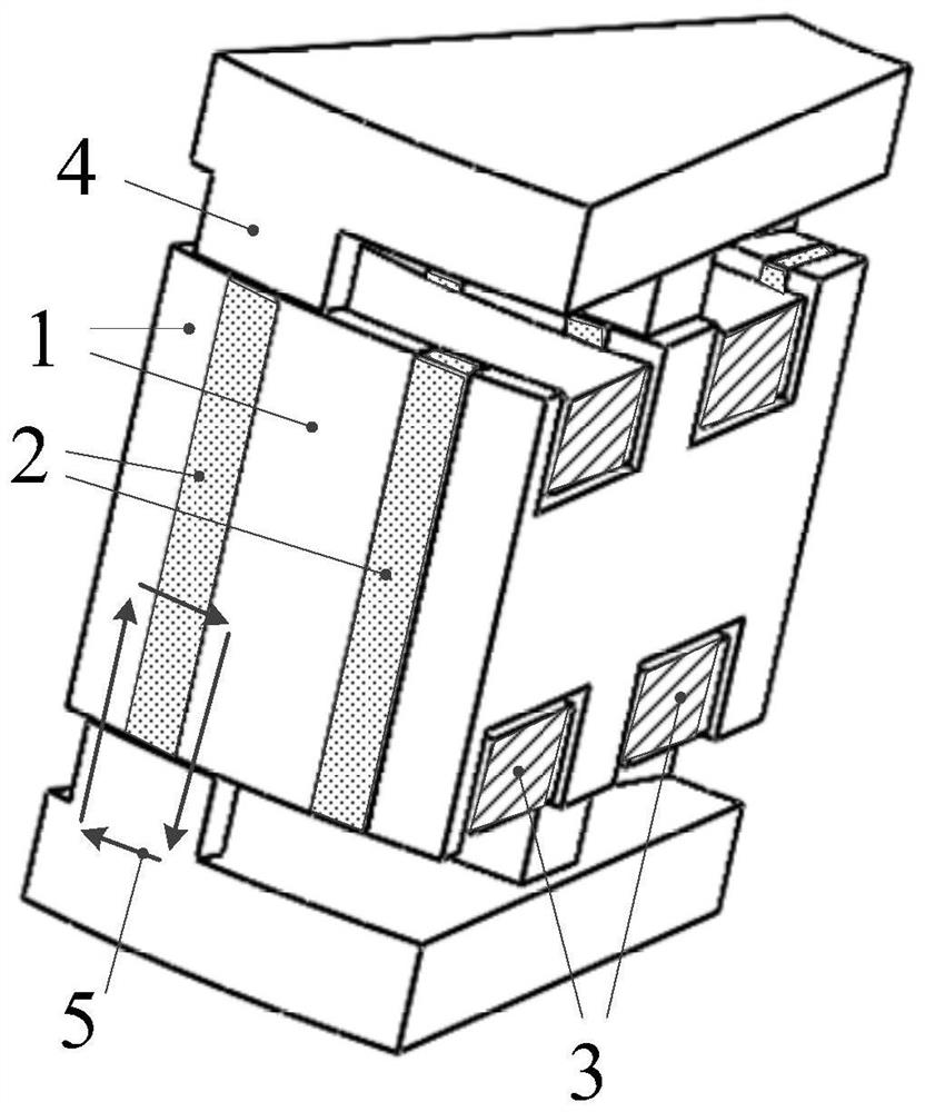
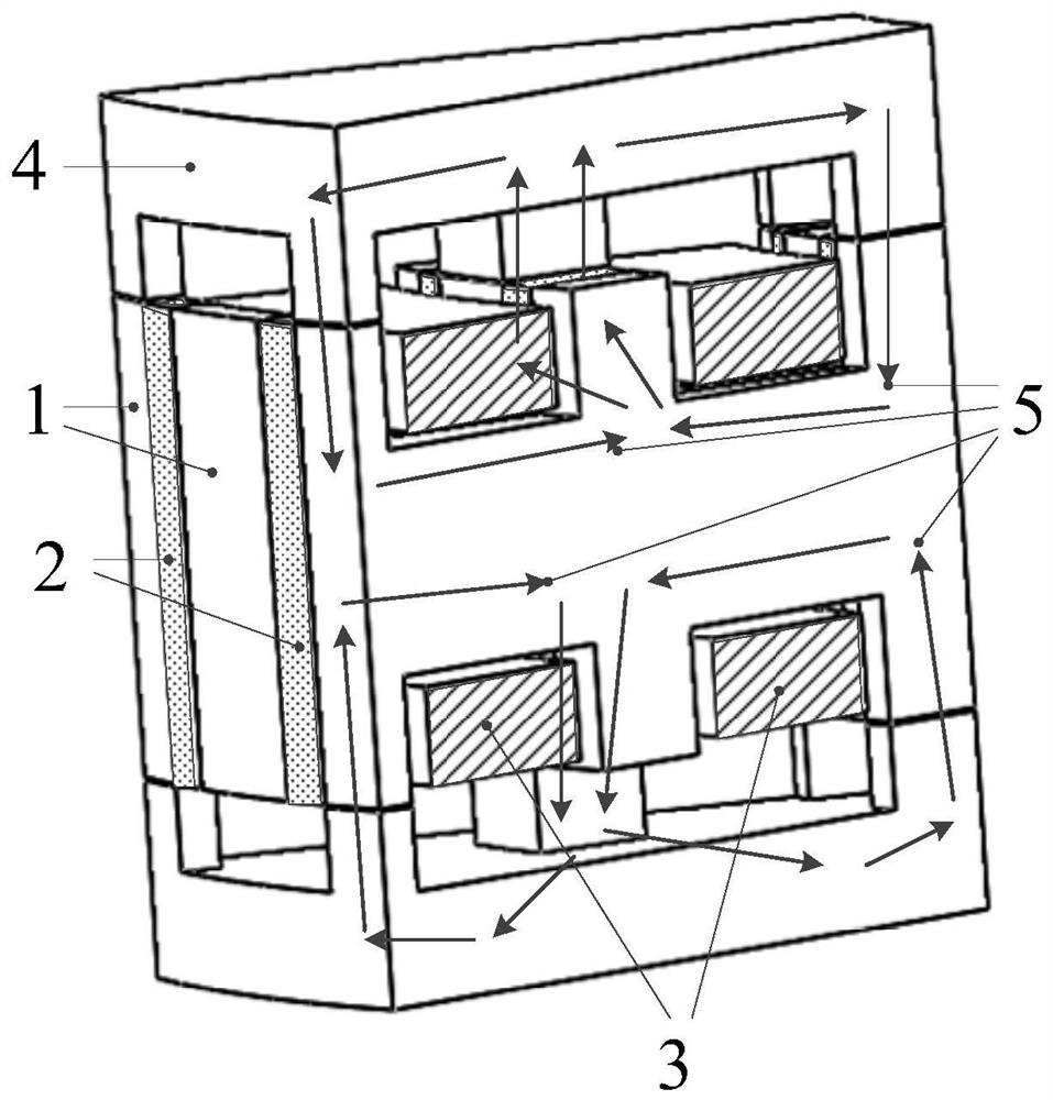
[0039] Those skilled in the art can understand that the accompanying drawing is only a schematic diagram of an embodiment, and the modules or processes in the accompanying drawing are not necessarily necessary for implementing the present invention. The technical solution of the present invention will be described below by taking 16 pairs of poles and three-phase magnetic concentration type bilateral passive rotor transverse flux permanent magnet motor as an example. This example of 16 pairs of poles and three-phase magnetic concentration ty...


PUM


Abstract

The invention discloses a three-phase magnetism gathering type bilateral passive rotor transverse flux permanent magnet motor, which comprises a stator composed of double H-shaped stator cores and double H-shaped permanent magnets, an axially upper and lower first and second rotors, and an armature coil. The double H-shaped permanent magnets are magnetized along the circumferential direction and the magnetization directions of two adjacent double H-shaped permanent magnets are opposite. The armature coils are wound in the grooves formed after the stator cores and permanent magnets are alternately arranged. Two coils are connected in reverse series to form a phase winding. Both the first and second rotors have 3 turns of radially arranged rotor teeth, which are connected together by a disc-shaped yoke, and the adjacent two turns of rotor teeth are staggered by 180 / n mechanical angle. When the armature winding is interlinked with the maximum permanent magnet flux linkage, the stator teeth and the rotor teeth are completely overlapped, and the permanent magnets adjacent to the same stator core are simultaneously concentrated to the stator core along the circumference, and each permanent magnet provides an effective magnetomotive force. The magnetic circuit can go to the upper and lower rotors through the axial air gap, which improves the utilization rate and torque density of the permanent magnets.

Description

technical field [0001] The invention relates to a three-phase magnetism-concentrating bilateral passive rotor transverse flux permanent magnet motor, which belongs to the technical field of transverse flux motors. Background technique [0002] The transverse flux motor structure was proposed by German professor Herbert Weh in the early 1980s, which can fundamentally improve the torque density. In traditional permanent magnet motors, the slots of the stator are on the same cross-section. If the cross-sectional area of ​​the coil is increased, the width of the teeth will be reduced, and the magnetic flux will be reduced due to saturation, and the slot sizes are mutually restricted. The stator teeth and armature coils of transverse flux permanent magnet motors are perpendicular to each other in space, the tooth width and coil cross-sectional size are independent of each other, and the magnetic circuit and circuit are decoupled, so higher torque density and power density can be ...

Claims


Application Information

Patent Timeline
Patent Type & Authority Patents(China)
IPC IPC(8): H02K16/02H02K1/18H02K1/14H02K1/27H02K1/24H02K1/02H02K3/28H02K3/18
CPCH02K1/02H02K1/14H02K1/18H02K1/24H02K1/2793H02K3/18H02K3/28H02K16/02H02K2201/12H02K2213/03
Inventor 陈志辉陈佳馨段津津张昌锦文力明庆永
Owner NANJING UNIV OF AERONAUTICS & ASTRONAUTICS
Why Eureka
Try Eureka