Coil panel of induction cooker and winding method thereof

A technology for coil coils and induction cookers, which is applied to coil devices, household stoves/stoves, electric heating fuels, etc. It can solve the problems of heating blind areas, susceptibility to uneven heating, large area, etc., achieve thin wire coil thickness, reduce heating blind areas, Effect of increasing coil winding density

Pending Publication Date: 2019-09-10
大红鹰商业管理(中山)有限公司
View PDF2 Cites 0 Cited by
  • Summary
  • Abstract
  • Description
  • Claims
  • Application Information

AI Technical Summary

Problems solved by technology

The technical solution of the present invention improves the first winding in the middle of the coil base so that the diameter of the inner ring is less than 12mm, thereby greatly reducing the area of ​​the blind area in the middle of the coil and improving the heating uniformity of the electromagnetic cooking utensils. However, the existing Technology 2 still has a heating blind area. The existing design 2 does not set a winding slot for each coil of the coil. It can be seen from the drawings of the existing design 2 that the existing design 2 is set by setting a stopper. To fix the position of the second winding coil, this will result in a large area without coil coils in the center of the second winding coil, and the second winding coils are arranged at intervals, which also leads to gaps between the coils, so there is a heating dead zone.
An induction cooker with a heating blind zone is prone to uneven heating when frying food, resulting in some parts of the fried food being mushy, but some places are still underheated. Therefore, an induction cooker coil plate that has no heating blind zone and can be heated evenly is needed.

Method used


Image

  • Coil panel of induction cooker and winding method thereof
  • Coil panel of induction cooker and winding method thereof
  • Coil panel of induction cooker and winding method thereof

Examples


Embodiment 1

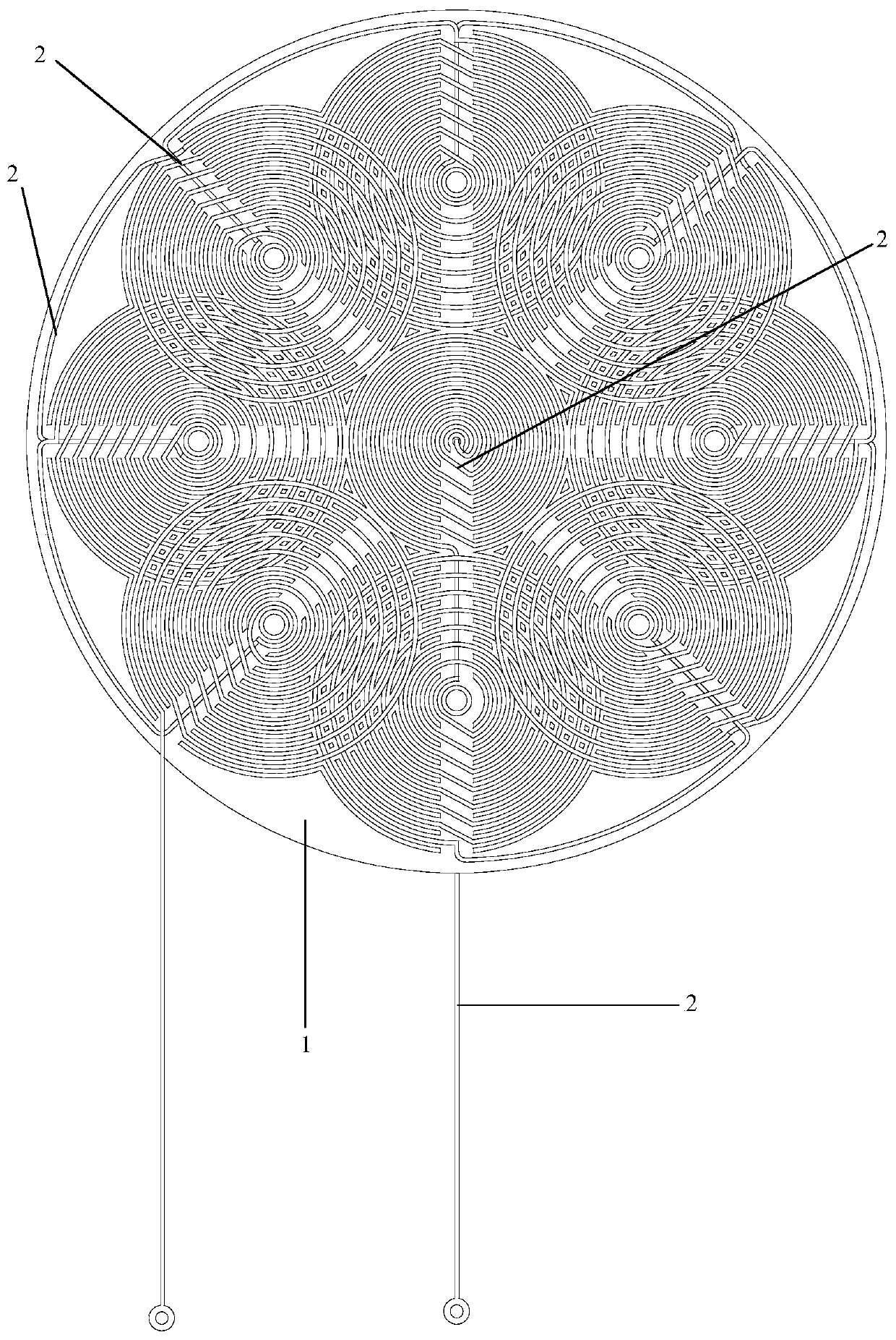
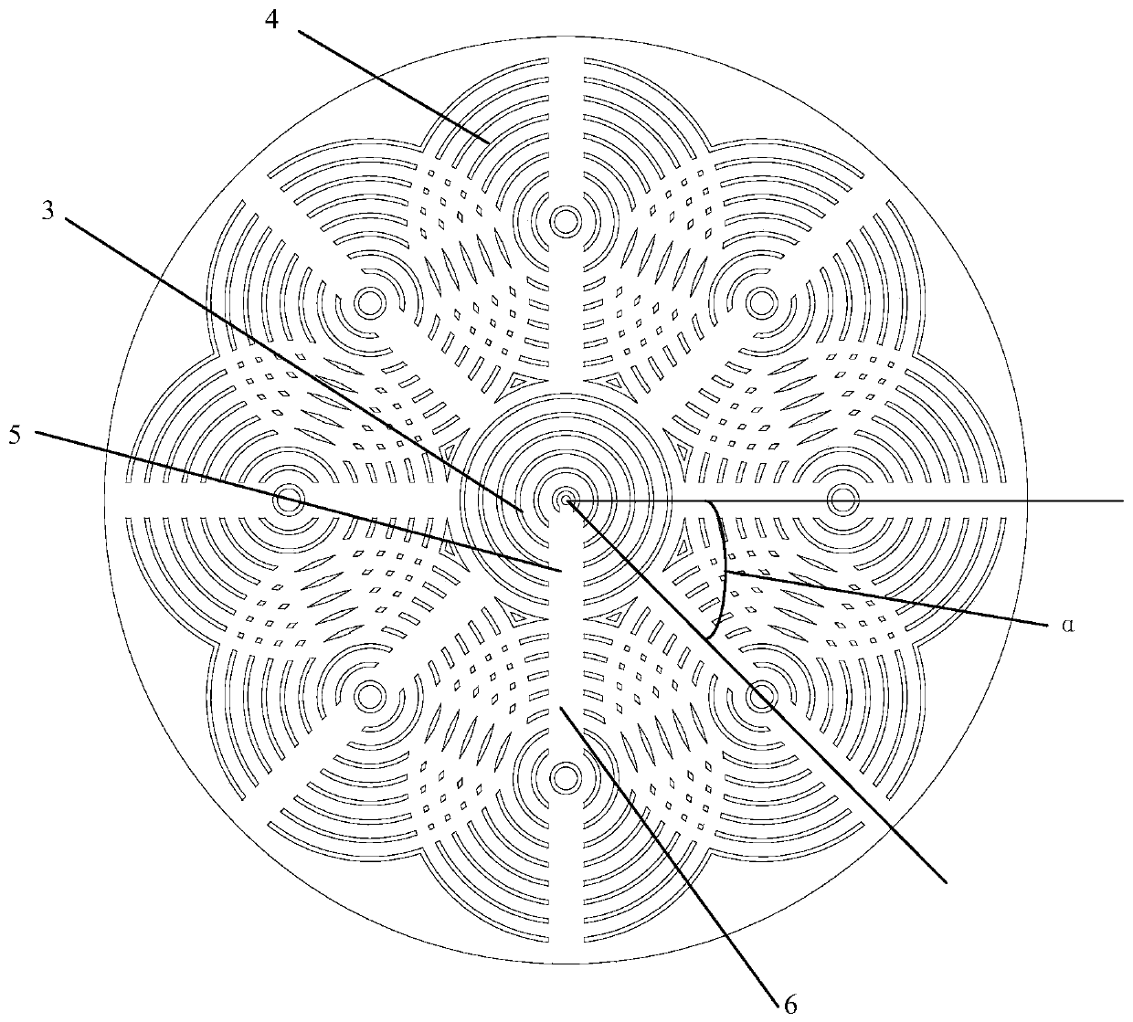
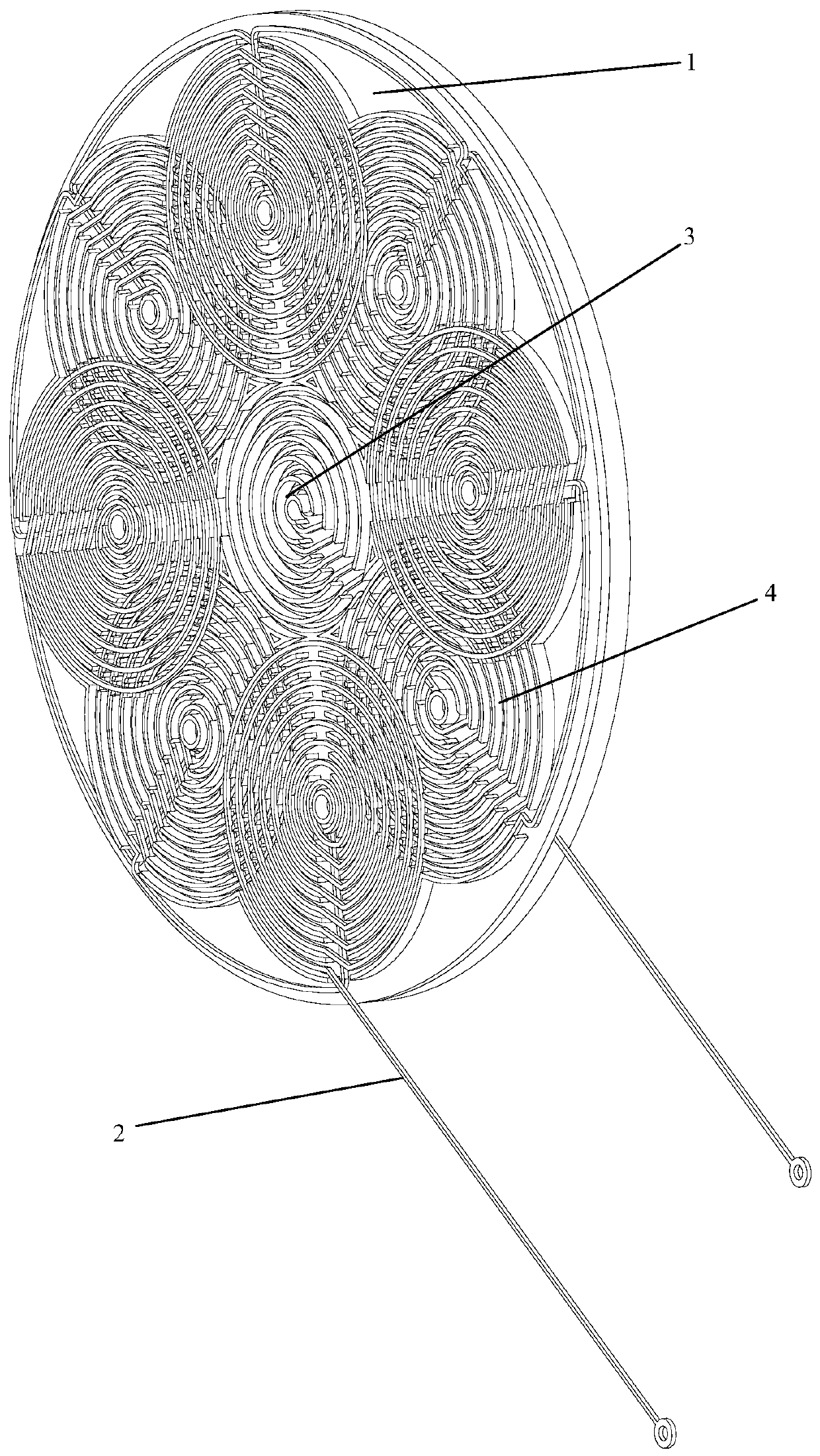
[0031] In order to solve the above technical problems, the present invention is implemented in the following manner, as shown in the figure: an induction cooker coil plate, which includes a coil base 1 and an enameled wire 2; the coil base 1 is provided with a wire groove for coiling the enameled wire 2 The wire groove includes a central wire groove 3 and a plurality of surrounding wire grooves 4 evenly arranged around the center wire groove 3; the center wire groove 3 includes a plurality of circular wire grooves centered on the center of the wire reel base; the surrounding wire groove 4 includes multiple There are annular wire grooves with a common center, and adjacent surrounding wire grooves 4 overlap each other.

[0032] Further, the center of the circle around the slot 4 is set on a circle with the center of the center slot 3 as the center.

[0033] Further, the radius of the circle around the center of the wire groove 4 is greater than the radius of the centerline groove 3 a...


PUM


Abstract

The invention relates to a coil panel of an induction cooker, comprising a coil panel base and enameled wires. The coil panel is characterized in that the coil panel base is provided with wire slots for coiling the enameled wires; the wire slots include a central wire slot and a plurality of circumferential wire slots uniformly arranged around the central wire slot; the central wire slot includesa plurality of annular wire slots centered around the center of the coil panel base; and each annular wire slot includes a plurality of annular wire slots having a common center, and the adjacent annular wire slots overlap with each other. There is no blind area of heating, and the heating is uniform. Especially when fried food is heated, the degree of heating is consistent in different areas, andno part of the food will be burnt.

Description

Technical field [0001] The invention relates to the technical field of gas cookers, in particular to an induction cooker coil plate. Background technique [0002] The coil disk of the existing induction cooker is set in a circular shape, and the coil is wound on the coil disk in a loop, but the existing coil has a heating blind zone. The authorized announcement number is CN203378076U, and the name of the invention is the prior art of a multi-coil uniform heating electromagnetic coil. 1 discloses a multi-coil uniform heating electromagnetic coil, which consists of a coil base and several evenly distributed on the coil base The small coil is composed of a magnetic core, a winding frame and a coil. The coil is arranged on the winding frame. The coil and the coil are wound by an enameled wire or each coil is wound separately and passes through the point Welding connects the enameled wire between the coil and the coil. However, the prior art 1 still has a heating blind zone, the sma...

Claims


Application Information

Patent Timeline
IPC IPC(8): H05B6/36F24C7/06B21F3/08
CPCH05B6/36F24C7/062B21F3/08
Inventor 葛晓松
Owner 大红鹰商业管理(中山)有限公司
Why Eureka
Try Eureka