
Internal combustion engines with fuel injection nozzles having an additional mechanism for introducing a combustion-promoting medium into the combustion chamber

A medium and fuel technology, which is applied in the direction of bringing fuel into the engine, combustion engine, fuel injection device, etc. through high-pressure gas, which can solve the problem of combustion air entering the cylinder, and achieve the effect of improving combustion and good controllability

Active Publication Date: 2021-08-27
ERWIN JUNKER GRINDING TECH
View PDF16 Cites 0 Cited by
  • Summary
  • Abstract
  • Description
  • Claims
  • Application Information

AI Technical Summary

Problems solved by technology

[0007] The disadvantages of these known internal combustion engines with a pressure accumulator are that the pressure accumulator additionally feeds additional combustion air into the intake tract of the internal combustion engine, the relatively high equipment costs and the large cross-section in the intake system. There is a relatively large volume of air that must be fed so that at least a portion of the additional combustion air enters the cylinder

Method used


Image

  • Internal combustion engines with fuel injection nozzles having an additional mechanism for introducing a combustion-promoting medium into the combustion chamber
  • Internal combustion engines with fuel injection nozzles having an additional mechanism for introducing a combustion-promoting medium into the combustion chamber
  • Internal combustion engines with fuel injection nozzles having an additional mechanism for introducing a combustion-promoting medium into the combustion chamber

Examples


Embodiment Construction

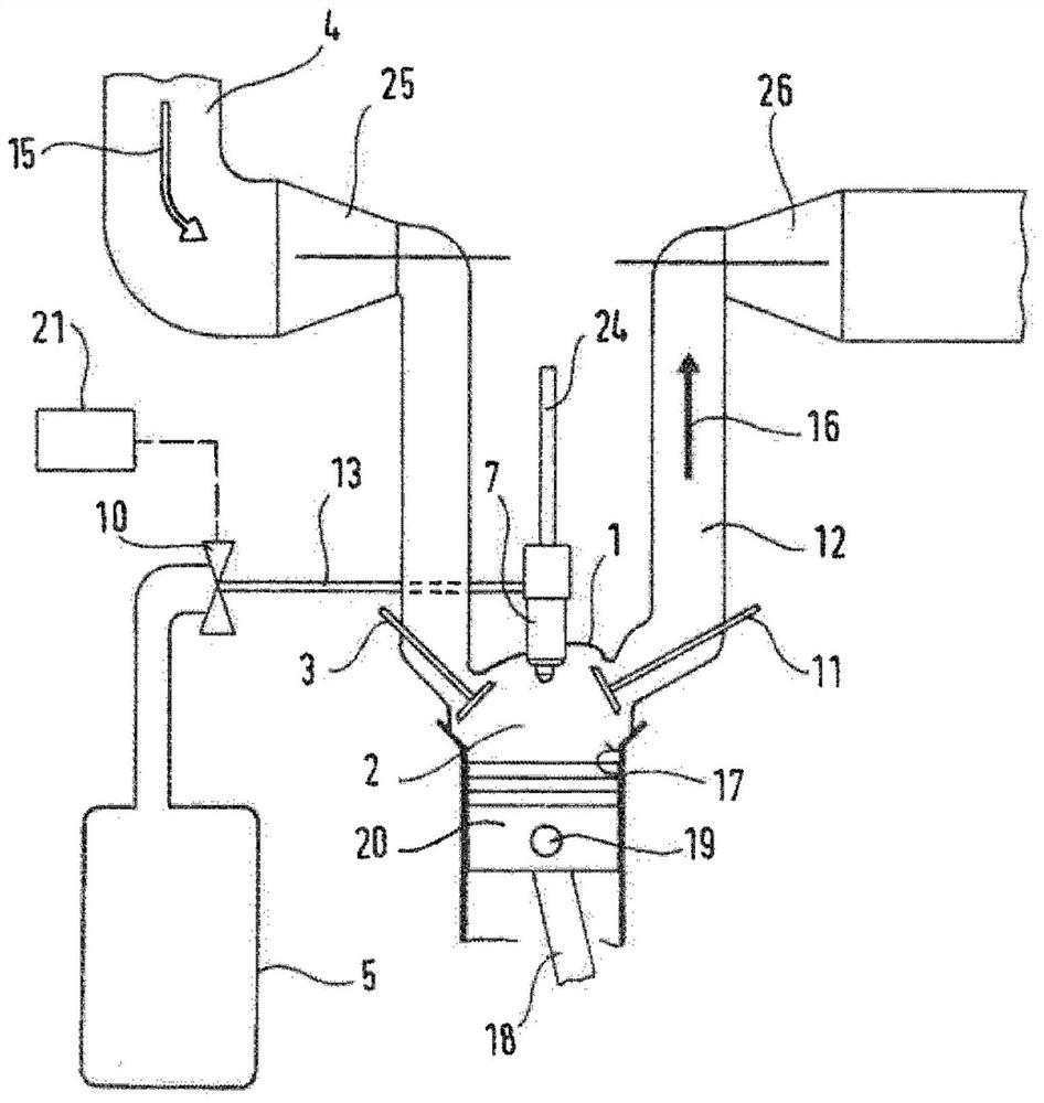
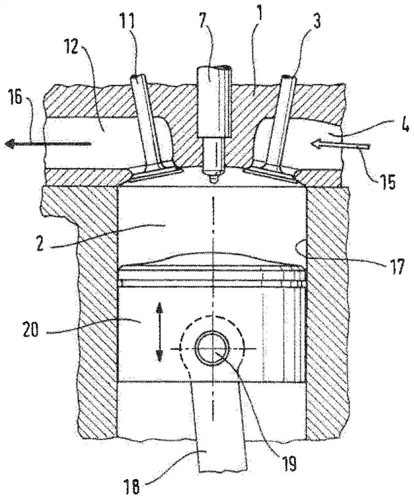
[0033] figure 1 Is a schematic view of a cylinder 2 of a reciprocating piston (engine) machine with an input valve 3 and an output valve 11 installed in the cylinder head 1. The input air 15 is conducted via the pressurized air line 4 or input line through a booster 25 for increasing the charging pressure and from there to the input valve 3 and, with the input valve 3 open, to the cylinder 2 middle. With the outlet valve 11 open, the combusted gases 16 after combustion flow through the outlet valve 11 into the exhaust gas line 12 and from there through the exhaust gas turbine 26 in which energy is extracted from the exhaust gas 16 for A pressure booster 25 arranged in the feed line 4 is driven.

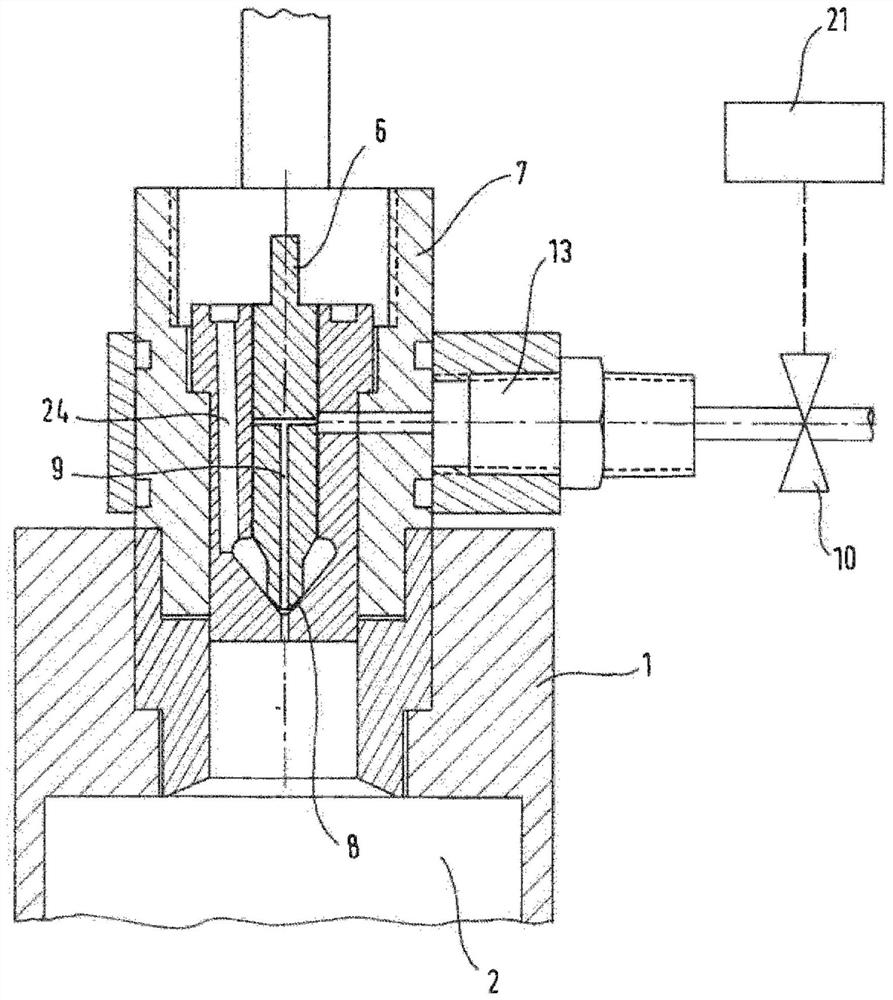
[0034] Also arranged in the cylinder head 1 is an injection nozzle 7 through which fuel is injected into the cylinder via a fuel line 24 for combustion of the fuel. Adjoining the injection nozzle 7 is a medium line 13 for a gaseous or liquid medium which is fed through the injectio...


PUM


Abstract

According to a first aspect of the invention, an internal combustion engine of the constructional type of a reciprocating piston engine is presented, which has in its cylinder head (1) an inlet valve (3) for supplying the cylinder (2), through which combustion air can pass The input valve feeds the cylinder (2) from the input line (4) connected to the input valve (3); the pressure accumulator (5), from which additional medium that promotes combustion in the cylinder (2) can be controlled delivery to the cylinder (2); and injection nozzles (7) through which fuel can be injected into the cylinder (2). According to the invention, the additional medium is the combustion air-fuel mixture. The pressure accumulator (5) is connected to an injection nozzle (7) with a nozzle needle (6) and additional medium can be introduced into the cylinder (2) in a controlled manner by means of the injection nozzle (7). According to a second aspect of the invention, a method is presented for additionally introducing an additional medium which promotes combustion in a cylinder of an internal combustion engine into a cylinder of a reciprocating piston engine, wherein the medium is delivered via injection nozzles.

Description

technical field [0001] The invention relates to a reciprocating piston internal combustion engine with the features of claim 1 and a method for introducing a combustion-promoting medium into a combustion chamber with the features of claim 11 . Background technique [0002] Reciprocating piston internal combustion engines are known in which the combustion air required for combustion is supplied to the cylinder via an inlet valve in the cylinder head of the cylinder, which is arranged at the end of the intake line through which the entire combustion air can pass together with flushing The air is delivered to the cylinder together. In conventional constructions, the internal combustion engine has an injection nozzle which has a nozzle needle inside it, by means of which the delivery of fuel into the cylinder is controlled. It is also known, in order to control or increase the torque of internal combustion engines and for controlling and improving the cold start behavior of suc...

Claims


Application Information

Patent Timeline
Patent Type & Authority Patents(China)
IPC IPC(8): F02D19/06F02M43/04F02M67/02F02M23/00
CPCF02M43/04F02M67/02F02D19/0694F02M2023/008Y02T10/30Y02T10/12F02M61/1886F02M67/12
Inventor 埃尔温·容克尔
Owner ERWIN JUNKER GRINDING TECH
Learn More