Radiator element

a technology of radiator element and radiator head, which is applied in the direction of gaseous heating fuel, combustion type, stove or range, etc., can solve the problems of brittle ceramic radiator, easy damage, and easy damage, and achieve the effect of reducing the risk of flashback damage, and reducing the service life of the radiator

Inactive Publication Date: 2005-05-24
SOLEBURY TECHN
View PDF26 Cites 47 Cited by
  • Summary
  • Abstract
  • Description
  • Claims
  • Application Information

AI Technical Summary

Benefits of technology

[0028]An object of the present invention is to provide a radiator element both mechanically and structurally robust to resist fatigue and damage commonly associated with radiant burner applications.
[0029]Another object of the present invention is to provide a radiator element facilitating the efficient combustion of a gaseous fuel-oxidant mixture.
[0030]A further object of the present invention is to provide a radiator element facilitating the efficient radiation of thermal energy.
[0032]Several advantages are noteworthy with the present invention. Metal foam radiators are more resistant to mechanical damage associated with under-fired and over-fired fuel-oxidant mixtures. Metal foam radiators are resistant to heat related fatigue. Metal foam radiators facilitate a more complete combustion within the firing surface. Metal foam radiators are more radiant efficient as a result of a more complete combustion of fuel-oxidant within the radiator. Irregularities along the surface of the metal foam enhance radiation performance particularly in an omni-directional sense.

Problems solved by technology

However, ceramic radiators are brittle, easily damaged during handling, and susceptible to flashback induced damage.
Metal-based radiator elements are disclosed within the arts, however limited to screens, nettings, woven and knitted yarns, woven fibers, and mechanically-drilled plates.
Screens, nettings, yarns, and fibers are structurally weak and susceptible to deflection and warp when heated to an elevated temperature for a sustained period.
Screens, nettings, yarns, fibers, and drilled plates frustrate the combustion of a gaseous fuel-oxidant mixture within the radiator element thereby reducing burner efficiency.
Consequently, metal radiators lack the robustness required to resist fatigue and damage and / or fail to efficiently generate and radiate thermal energy.

Method used


Image

  • Radiator element
  • Radiator element
  • Radiator element

Examples


Embodiment Construction

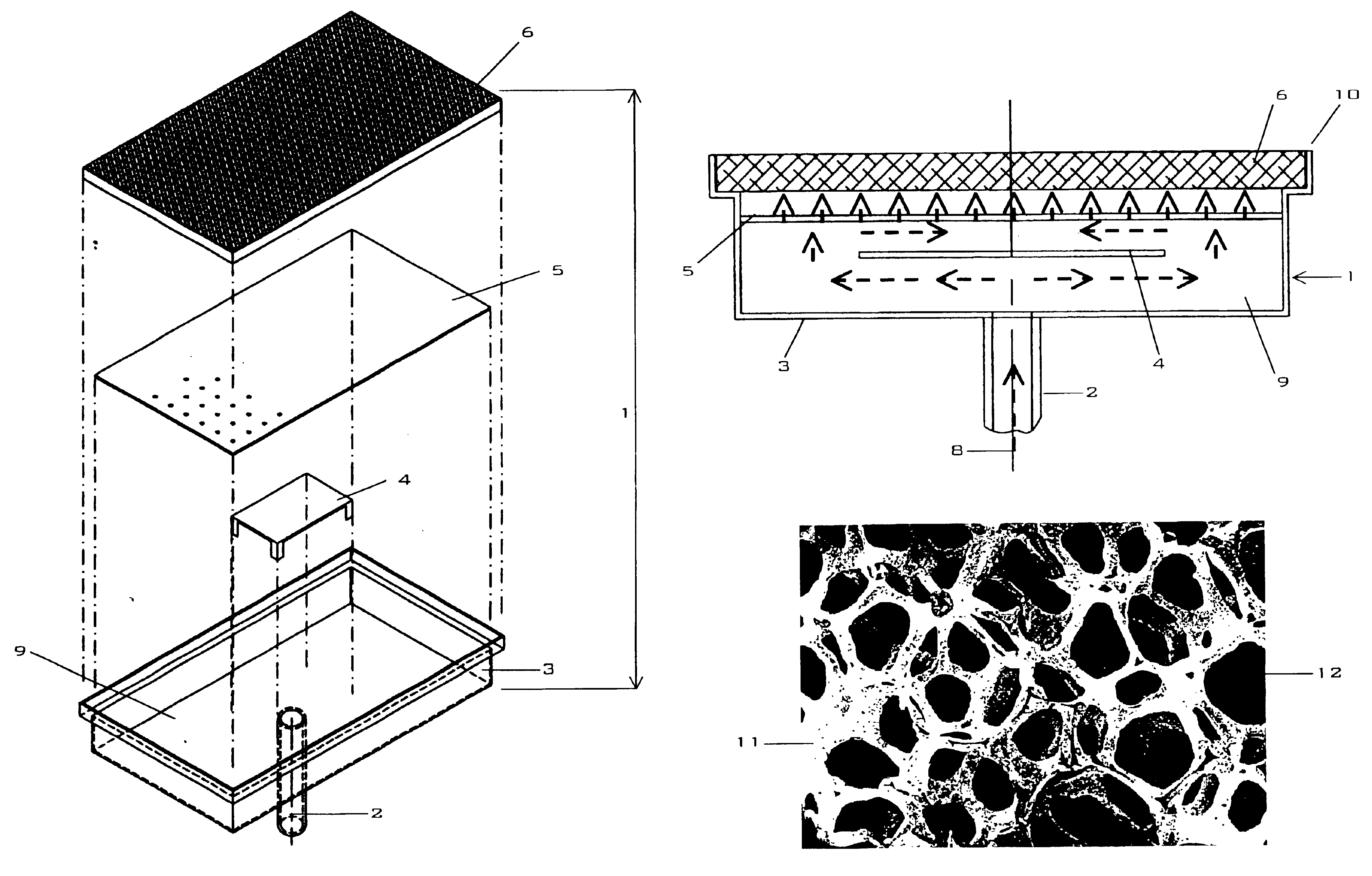
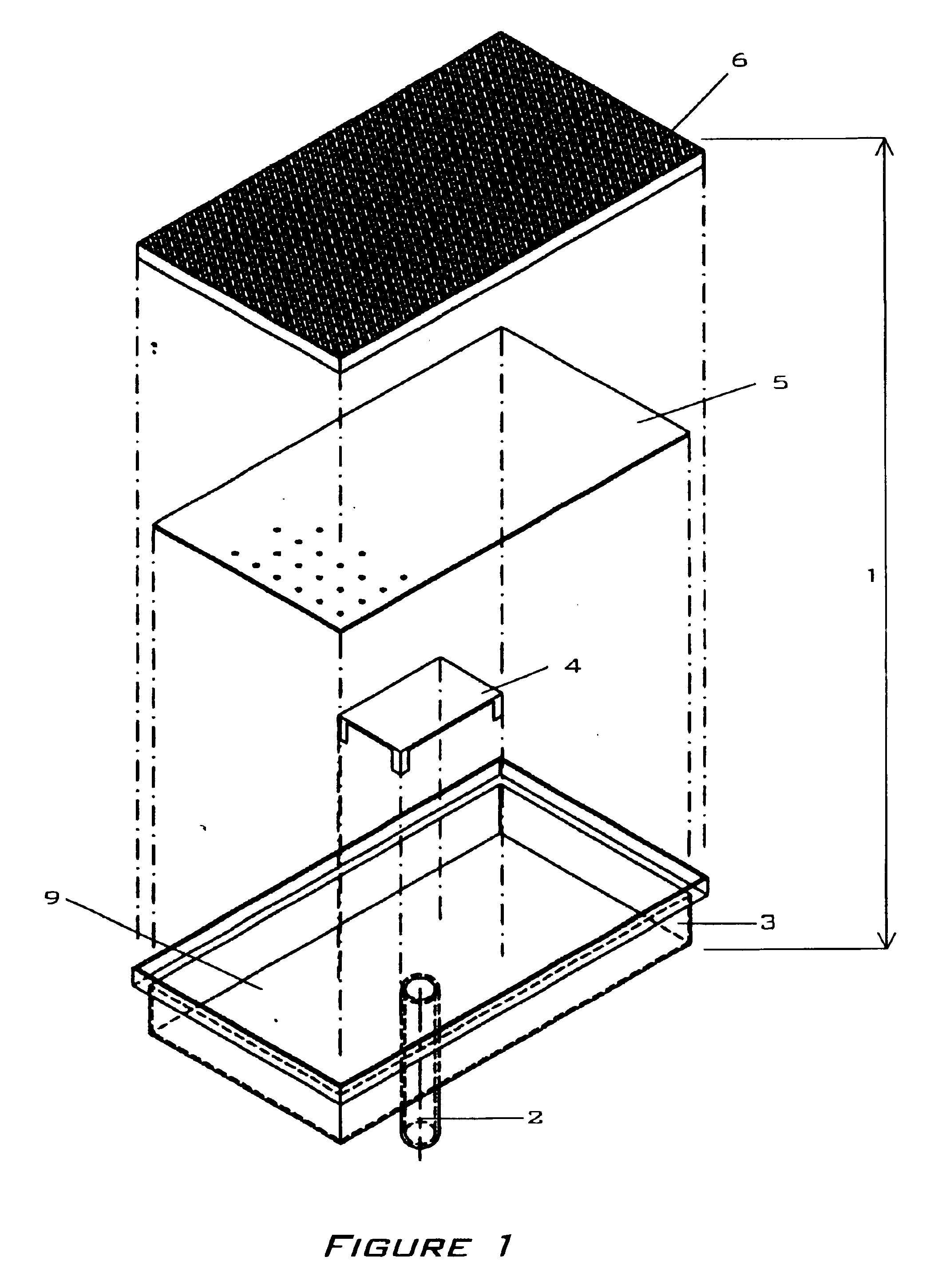
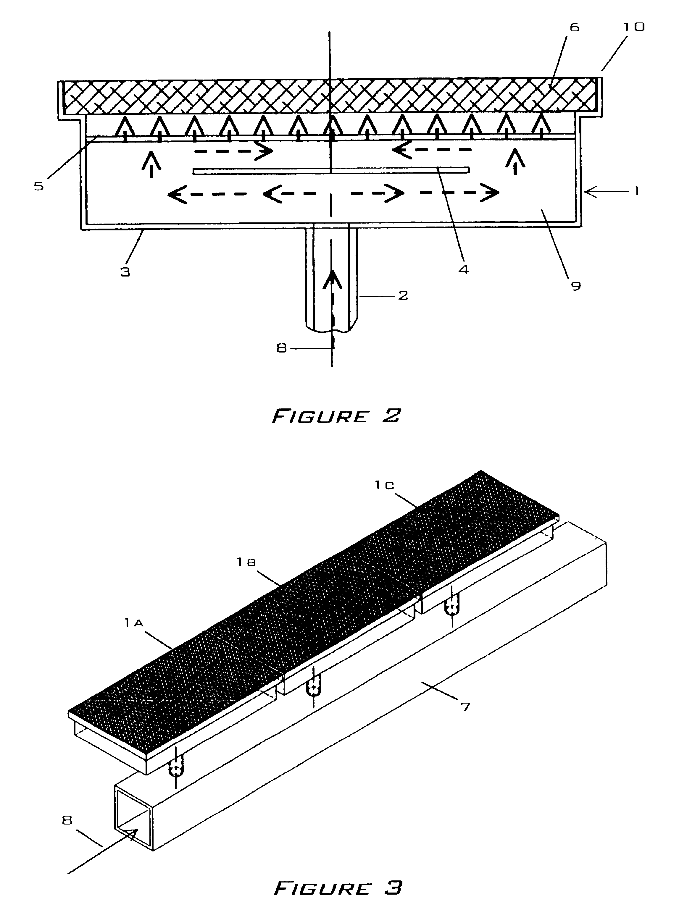
[0033]FIGS. 1, 2, and 3 describe the application of the present invention to a radiant burner 1. While planar applications are shown and described other shapes including but not limited to cylinders and tubes are also possible. FIG. 4 shows an exemplary metal foam embodiment of the present invention.

[0034]FIGS. 1 and 2 show a typical burner 1 comprised of an inlet 2, a plenum 3, a baffle element 4, a diffuser element 5, and a radiator element 6. FIG. 3 shows the arrangement of several burners 1a, 1b, 1c along a single manifold 7 in an arrangement typically found in a textile dryer. An igniter device as understood in the art is mounted adjacent to the radiator element 6 as so to initiate combustion of a fuel-oxidant mixture 8.

[0035]The plenum 3 is comprised of a five-sided structure having an open front 10 over which a radiator element 6 is fixed. A typical plenum 3 is composed of a metal either cast, molded or formed via methods understood in the art. An inlet 2 is attached to one s...


PUM

PropertyMeasurementUnit
thicknessaaaaaaaaaa
average cell diameteraaaaaaaaaa
flame temperaturesaaaaaaaaaa

Abstract

The present invention is a radiator element composed of a metal foam for use within a radiant burner. The radiator element is comprised of a homogenous network about a plurality of inter-connected cells thereby forming a gas-permeable metal foam. The homogeneous network may be composed of a metal or metal alloy capable of withstanding combustion temperatures typical of fuel-air reactions and resisting damage produced by flashback. Inter-connected cells include irregular-shaped voids, circular-shaped voids, and combinations thereof.

Description

CROSS REFERENCE TO RELATED APPLICATIONS[0001]This application claims benefit under 35 U.S.C. 119(e) from U.S. Provisional Application No. 60 / 323,446 filed on Sep. 19, 2001.FEDERALLY SPONSORED RESEARCH OR DEVELOPMENT[0002]None.BACKGROUND OF THE INVENTION[0003]1. Field of the Invention[0004]The present invention generally relates to a radiant burner fueled by a gaseous fuel-oxidant mixture. Specifically, the invention is a radiator element composed of a metal foam for use within a radiant burner.[0005]2. Description of Related Art[0006]Radiant burners are commonly employed for a variety of purposes including heating, drying, and decontamination in such industries as paper manufacture, textile processing, and food preparation.[0007]A typical burner is composed of an inlet attached to a plenum with a radiator element attached to the front of the burner. A baffle and diffuser are provided within the plenum in some embodiments so to optimize the flow of a fuel-oxidant mixture onto the rad...

Claims


Application Information

Patent Timeline
Patent Type & Authority Patents(United States)
IPC IPC(8): F23D14/16F23D14/12
CPCF23D14/16F23D2212/20F23D2203/1055
Inventor RATTNER, DAVIDO'LEARY, JOSEPH A.
Owner SOLEBURY TECHN
Why Eureka
Try Eureka