Hydrogen feed method and systems for engines

a technology of hydrocarbon feed and engine, which is applied in the direction of machines/engines, mechanical equipment, combustion air/fuel air treatment, etc., can solve the problems of increasing the complexity of state of the art internal combustion engine systems, the increase of the cost of implementation, and the increase of the cost of fuel consumption. , to achieve the effect of increasing the combustion of hydrocarbons and promoting efficient combustion

Inactive Publication Date: 2014-06-03
GO GREEN HYBRID FUEL SYST
View PDF19 Cites 2 Cited by
  • Summary
  • Abstract
  • Description
  • Claims
  • Application Information

AI Technical Summary

Benefits of technology

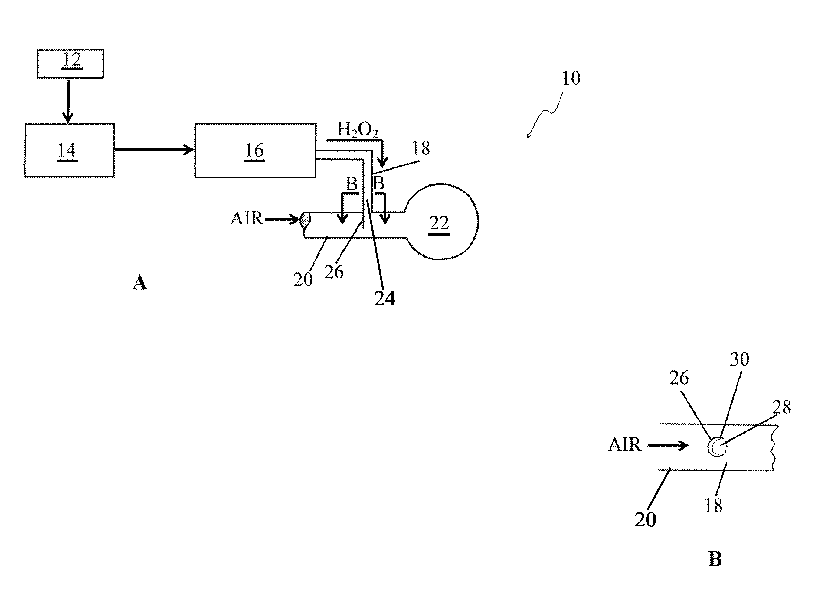
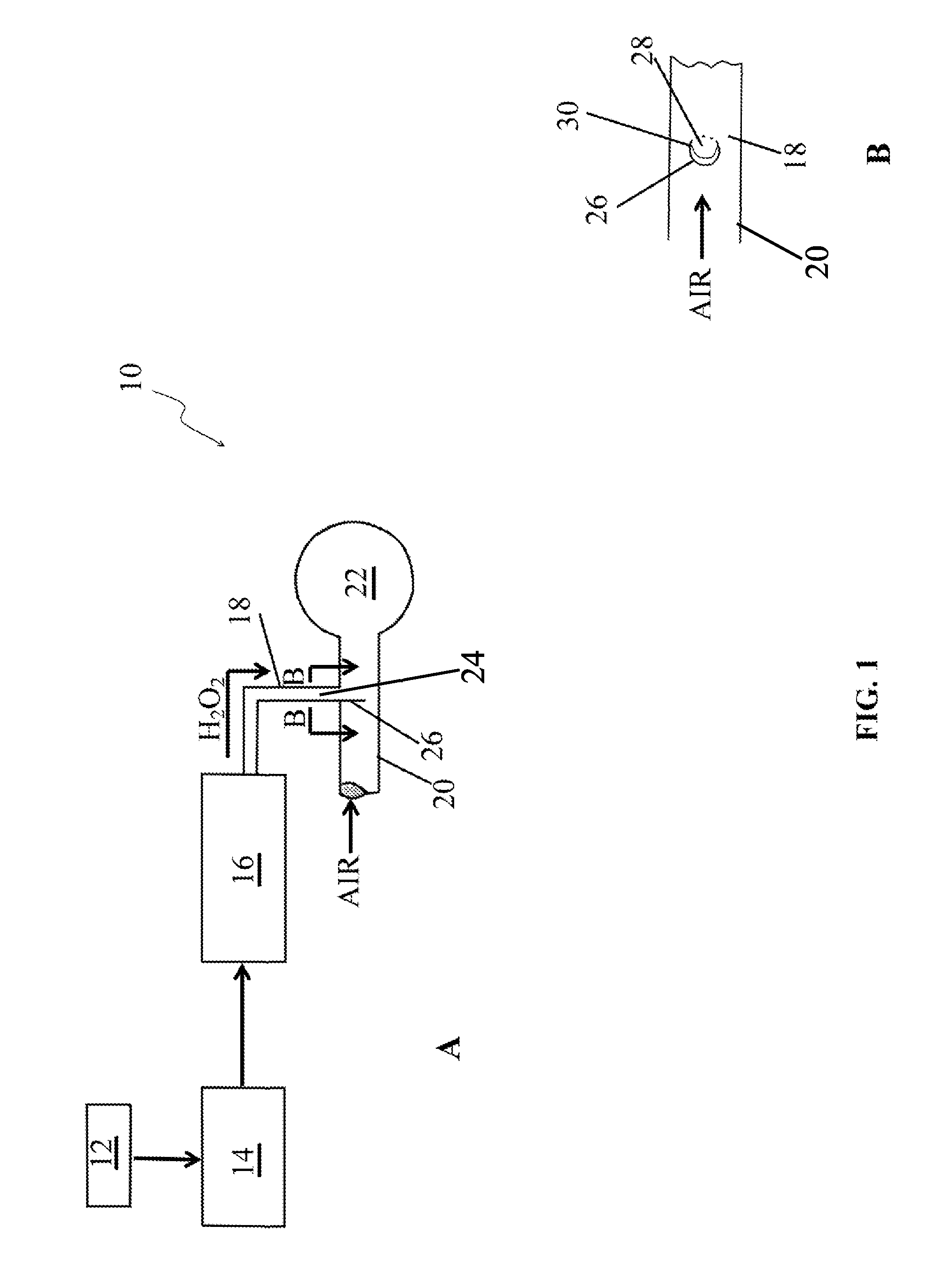
[0010]Another object of the invention is to provide a method for in situ production and direct injection of hydrogen gas into air intake manifolds of engines. A feature of the invention is the electrolysis of modified water. An advantage of the invention is that the modified water is a year-round feedstock for the production of on-demand hydrogen gas, thereby eliminating the problems associated with storage of not yet used hydrogen.
[0011]Another object of the present invention is to provide a source of oxygen enriched gas to promote efficient combustion. A feature of the invention is the utilization of oxygen byproduct gas from the production of hydrogen as a combustion enhancing gas. An advantage of the invention is an increase in combustion of hydrocarbons within an internal combustion engine by the increase of oxygen in the air intake of the internal combustion engine.
[0012]Briefly, the invention provides a method for enriching air with hydrogen for subsequent use by internal combustion engines, the method comprising supplying a modified form of water; electrolyzing the water to produce hydrogen gas; mixing the gas with air to produce a hydrogen-air mixture; and injecting the mixture into the air intake of a combustion engine.
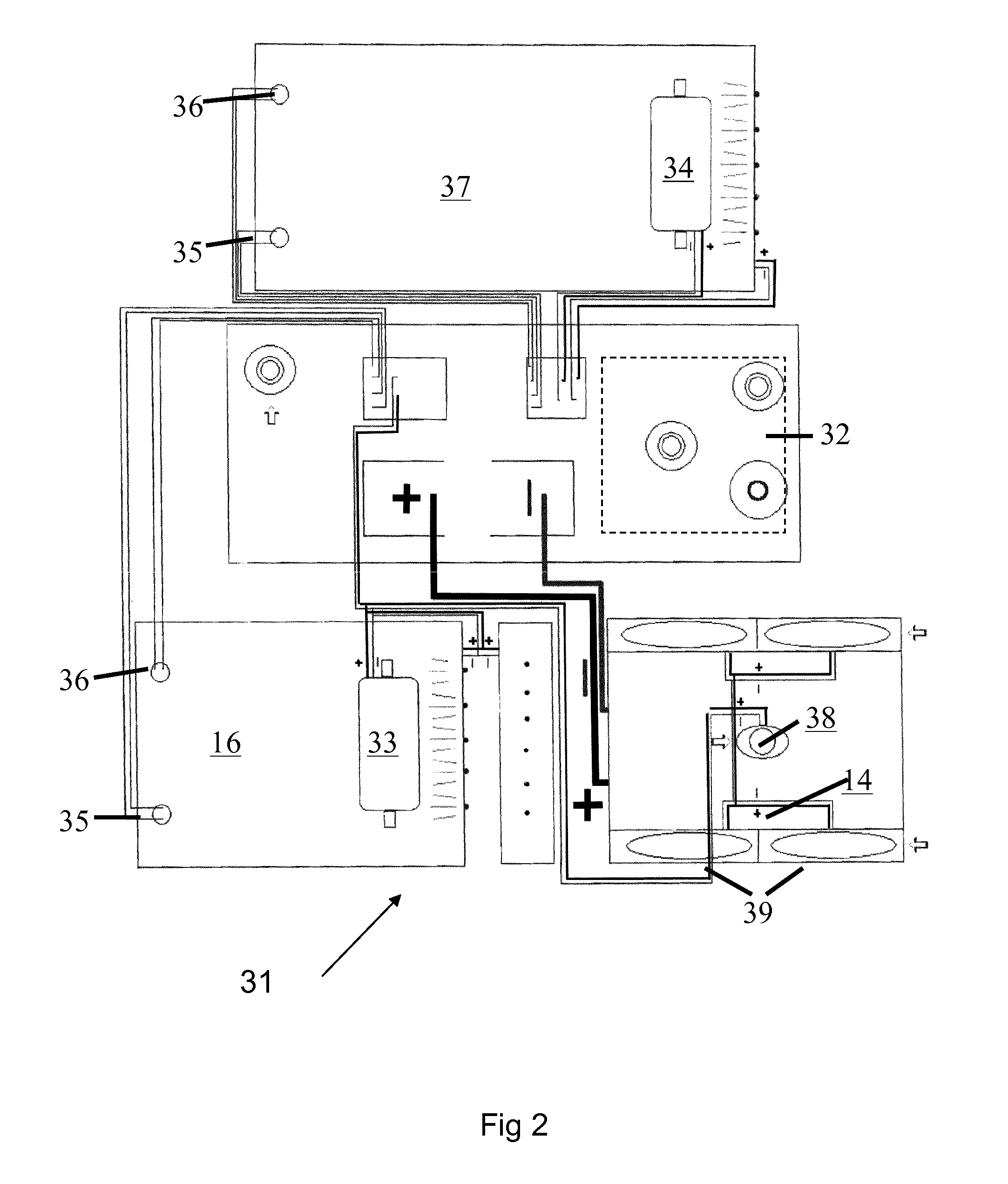
[0013]Also provided is a system for enriching internal combustion engine air intake with hydrogen gas, the system comprising modified water; a means for producing hydrogen gas from the modified water; a means for mixing the hydrogen gas with air to create a mixture; and a means for injecting the mixture into the air intake system of the engine.

Problems solved by technology

State of the art systems for internal combustion engines have become increasingly complex, with the latest developments including an amalgam of hybrid vehicle drive trains, complex fuel reforming systems and alternate fuel storage systems.
Further, these systems are extremely complex and therefore expensive to implement at this time.
Further, this device uses hydrocarbon based fuel, a costly fuel as its main source of energy.
Since the system uses distilled water, the system relies on the conductivity of pure water, which is low due to a limited source of conductive ions.
Further, should the system stop working due to loss of additives or system malfunction, the underlying drive trains should continue to function while the alternate fuel system is unavailable.

Method used


Image

  • Hydrogen feed method and systems for engines
  • Hydrogen feed method and systems for engines
  • Hydrogen feed method and systems for engines

Examples


example 1

Fluid Example 1

[0070]The three-season Hydrogen Reaction Fluid is currently formulated using about 0.64% weight percentage of an alkali hydroxide (such as sodium hydroxide) dissolved in deionized water.

[0071]The winterized versions of the reaction fluid (i.e., where ambient temperatures range from about −50 F to 32 F), have 2-Propanol as a component of its composition. The alcohol's presence is primarily to lower the freezing temperature of this mixture. Different freeze protection levels contain different alcohol percentages. An embodiment of the winter blend also contains between about 50% and 500% more chemical salts, preferably between about 75 and 300% and most preferably between about 100 and 200% more chemical salts to achieve the hydrogen production rates seen when the 3-season fluid blend is used.

example 2

Fluid Example 2

[0072]The winter blend (wherein the blend accommodates 0° F. average ambient temperatures) is currently formulated using from about 2% to about 5% by weight of alkali hydroxide (such as sodium hydroxide), preferably 2.2% to 2.8%, and most preferably about 2.3% by weight sodium hydroxide (“Alkali chemical salt”). The hydroxide is substantially completely dissolved in the deionized Water (from between 60% to 70% by formulation weight, preferably 65% to 70% and most preferably 68.7% by formulation weight). From about 15% to 40% by weight, preferably 20-35% by weight, and most preferably about 27-30% by weight of the 2-Propanol is added to the alkali hydroxide spike water and mixed to a homogeneous blend of the three ingredients.

example 3

Fluid Example 3

[0073]A second winter blend (wherein the blend accommodates ambient temperatures which average minus 10° F. utilizes between 2% and 4% by weight of alkali metal salt, preferably between about 1% and 2% and most preferably about 1.4 to 1.5% weight percentage. The salt is substantially completely dissolved in the deionized water between 50 and 70% by formulation weight, preferably between 55 and 65% and most preferably about (63% by formulation weight). Between approximately 20-45% by weight, preferably 30-40% and most preferably between about 35% and 36% by weight of the 2-Propanol is added and the three constituents homogenized.


PUM


Abstract

A method for enriching air with hydrogen for subsequent use by internal combustion engines is discussed. The method begins with supplying a modified form of water. Subsequently, the method continues with electrolyzing the water to produce hydrogen gas. Next, the method involves mixing the gas with air to produce a hydrogen-air mixture, and injecting the mixture into the air intake of a combustion engine. Also discussed is a system for enriching internal combustion engine air intake with hydrogen gas. The system uses modified water, an electrolysis unit for producing hydrogen gas from the modified water. The system mixes the gas with ambient air to create a mixture, and a venturi-based injector introduces the mixture into the air intake system of the engine.

Description

BACKGROUND OF THE INVENTION[0001]1. Field of the Invention[0002]This invention relates to a device and method for supplying hydrogen gas to an air intake system, and more particularly, this invention relates to a device and method for in situ production and utilization of hydrogen gas in internal combustion engines.[0003]2. Background of the Invention[0004]The need for increase fuel efficiency and lower emissions has reached a critical state. State of the art systems for internal combustion engines have become increasingly complex, with the latest developments including an amalgam of hybrid vehicle drive trains, complex fuel reforming systems and alternate fuel storage systems.[0005]Current fuel reforming designs utilize liquid petroleum fuels in attempts to crack those feedstocks to single carbon moieties, or even hydrogen gas. While reforming processes provide a source of clean fuel, hydrogen, green house gases and related pollutants are produced. Further, these systems are extrem...

Claims


Application Information

Patent Timeline
Patent Type & Authority Patents(United States)
IPC IPC(8): F02B1/04F02B63/00F02M27/02F02B63/04F02B43/10F02B43/08F02B75/16F02M25/12F02B77/13
CPCF02M27/02F02B43/08F02B43/10F02B63/044F02B43/12Y02T10/32F02B75/16F02M25/12F02B1/04F02B77/13F02B2063/045F02B63/04Y02T10/121C25B1/06F02B2043/106C25B1/04C25B11/00Y02E60/36Y02T10/12
Inventor MINGILINO, CHRISBAILLEAUX, LEOCORRY, CHARLIEFORNARELLI, THOMASTUTT, TIMOTHY TKALMANOVSKY, ANATOLY
Owner GO GREEN HYBRID FUEL SYST
Why Eureka
Try Eureka