
Metal honeycomb heating element for gas stove

A honeycomb heating element and metal honeycomb technology, applied in the field of cookers, can solve the problems of honeycomb body porosity reduction, limited combustion efficiency, poor cooking experience, etc., and achieve the effects of high-efficiency combustion, combustion exhaust emission, and fast heating speed

Pending Publication Date: 2019-11-12
VATTI CORP LTD
View PDF0 Cites 0 Cited by
  • Summary
  • Abstract
  • Description
  • Claims
  • Application Information

AI Technical Summary

Problems solved by technology

[0003] 1. The porosity of the honeycomb body will decrease, which is not conducive to ejection and limits the further improvement of combustion efficiency;
[0004] 2. More consumables, slower heating, and worse cooking experience

Method used


Image

  • Metal honeycomb heating element for gas stove
  • Metal honeycomb heating element for gas stove
  • Metal honeycomb heating element for gas stove

Examples


Embodiment 1

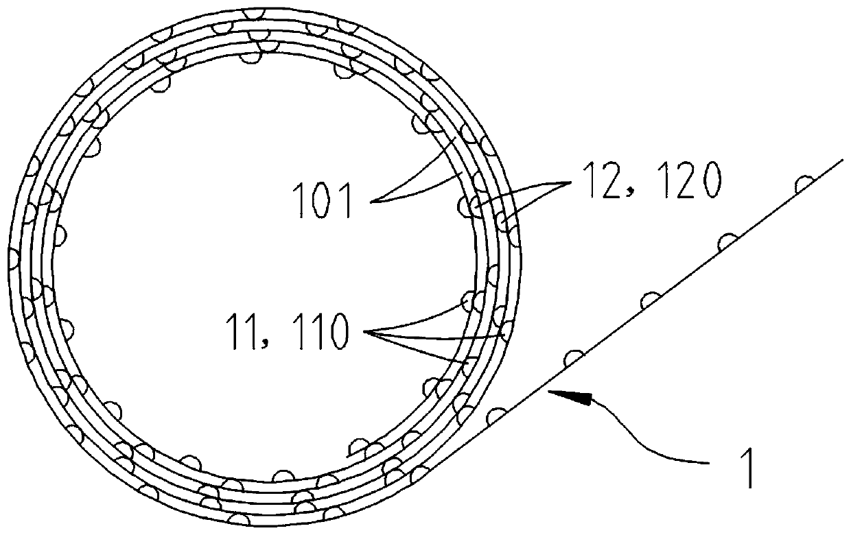
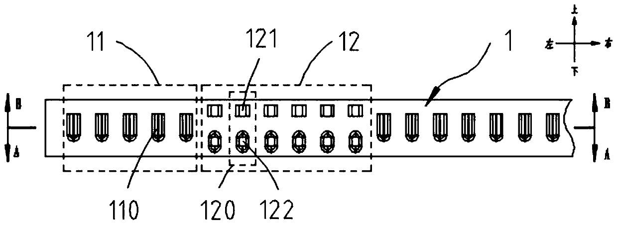
[0030] Such as Figure 1-2 As shown, a metal honeycomb heating element for a gas cooker includes a metal strip 1. On the same side of the metal strip 1, there are alternately arranged protrusion groups I11 and II12, and the metal strip 1 is coiled to form A honeycomb heating element with a plurality of coils, the protrusion group I11 and the protrusion group II12 are respectively arranged in any two adjacent coils, and a hole 101 for gas passage is formed between the adjacent coils, and the gas flows from the hole 101 is transferred to the upper surface of the honeycomb heating element for combustion. The protrusion group I11 and the protrusion group II12 include a plurality of protrusions 110, 120, the lower ends of the protrusions 110, 120 are closed, and the upper ends have openings to form a partial aperture 101. In this embodiment, the aperture 101 includes openings at the upper ends of the protrusions 110, 120, and air holes formed by the protrusions 110, 120 surrounding ...

Embodiment 2

[0040] Such as Image 6 As shown, the difference between this embodiment and Embodiment 1 is that the upper end of the sub-protrusion 122 is formed as an opening for the air outlet 103, and the lower end is closed. Specifically, the sub-protrusion 122 is integrally stamped and formed by the metal strip 1, and the upper end of the sub-protrusion 122 is cut and separated from the metal strip 1 to form an opening, and the lower end is closed. The other parts are the same as in Embodiment 1.

[0041] It can be seen that by providing the opening as the air outlet 103 at the upper end of the sub-protrusion 122, this is beneficial to further increase the pore 101, making the porosity of the metal honeycomb heating element higher, and is more beneficial to improving the combustion efficiency and heating effect.


PUM


Abstract

The invention discloses a metal honeycomb heating element for a gas stove. The metal honeycomb heating element for the gas stove at least comprises a metal strip, a boss set I and a boss set II are alternatively arranged on the metal strip, the metal strip is coiled to form a honeycomb heating element body with a plurality of coil rings, the boss set I and the boss set II are arranged on any two adjacent coil rings respectively, and holes for gas to pass are formed between adjacent coil rings. The boss set I and the boss set II comprise a plurality of bosses, the lower ends of the bosses are sealed, and openings are formed in the upper ends of the bosses. According to the metal honeycomb heating element for the gas stove , the the porosity of the lower end of the honeycomb body is low, gascan pass through the lower end of the honeycomb heating element body with a higher speed, the lower end of the honeycomb heating element body can be better cooled, and thus the purposes that flames are prevented from spreading to the lower end of the honeycomb heating element body, the burning stability is high, and backfire is not likely to occur are achieved; and besides, the porosity of the upper end of the honeycomb heating element body is high, it is beneficial to efficient burning of gas, the heating speed is high, and meanwhile it is beneficial to discharging of burning tail gas.

Description

Technical field [0001] The present invention relates to the technical field of stoves, and in particular to a metal honeycomb heating element for gas stoves. Background technique [0002] At present, the heating elements of infrared gas stoves on the market mainly include ceramic honeycomb and metal honeycomb heating elements. Among them, the metal honeycomb heating element is more and more popular with consumers because of its better resistance to cold and heat shock and better texture. Welcome. The metal honeycomb heating element is mostly made of one or more metal thin strips, but the dense metal strip has higher thermal conductivity than loose ceramics, and the heat is easier to move from the honeycomb panel to the lower side. Conduction, resulting in high temperature under the honeycomb panel. For the honeycomb body that is coiled by the metal strip and the pores have a uniform structure up and down, in order to prevent the flame from spreading to the lower side of the hon...

Claims


Application Information

Patent Timeline
Patent Type & Authority Applications(China)
IPC IPC(8): F24C15/24F23D14/46
CPCF24C15/24F23D14/46F23D14/147
Inventor 刘凯陈琦罗长兵潘叶江
Owner VATTI CORP LTD
Learn More