Large-bore, medium-speed diesel engine having piston crown bowl with acute re-entrant angle

a technology of large-bore, medium-speed diesel engine and crown bowl, which is applied in the direction of combustion engines, machines/engines, pistons, etc., can solve the problems of increasing the probability of being completely burned, increasing the likelihood of being burned in the following combustion event, and affecting the performance of the combustion process. , to achieve the effect of reducing nox formation, improving performance and emissions characteristics, and facilitating the combustion process

Active Publication Date: 2008-10-21
ELECTRO-MOTIVE DIESEL
View PDF27 Cites 46 Cited by
  • Summary
  • Abstract
  • Description
  • Claims
  • Application Information

AI Technical Summary

Benefits of technology

[0017]According to the present invention, an acute re-entrant angle crown bowl is provided for the piston crown of a large-bore diesel engine, yielding an improvement in performance and emissions characteristics. The key design variables of the acute re-entrant angle crown bowl according to the present invention include: re-entrant angle of the sidewall of the crown bowl, maximum and minimum crown bowl radii, crown bowl center depth, crown bowl surface angle, maximum crown bowl depth, squish height and piston squish face width.
[0018]For a given size large-bore diesel engine, breathing capacity, airflow, and fuel flow conditions, the acute re-entrant angle crown bowl facilitates the combustion process, resulting in lower NOx formation and enhanced oxidation of soot, hydrocarbons, and carbon monoxide emissions. By changing the fuel injection timing and injection characteristics (injection pressure, rate of injection, and spray angle), the acute re-entrant angle crown bowl offers the best balance trade-off of minimization of harmful emissions and performance optimization. For example, multiple injections through a high-pressure common rail injection can benefit from an acute re-entrant angle crown bowl with enhanced air movement and air utilization within the combustion chamber.
[0019]Recent advancements in high-temperature materials, manufacturing processes and fuel injection systems such as electronically controlled high-pressure common rail injection provides greater flexibility in designing piston bowl shapes for large-bore, medium speed diesel engines. The current invention discloses a piston bowl design with an acute re-entrant angle bowl shape taking advantages of the delineated advancements. When fuel injection event is properly matched with the acute re-entrant angle crown bowl shape, the spray combustion process can be optimized to achieve higher fuel efficiency and lower exhaust emissions simultaneously. For example, with multiple fuel injections per combustion event, an acute re-entrant angle crown bowl offers additional flexibility in controlling the mixing process, wherein the spray-induced flow field takes the shape of the crown bowl. Thus, it is more likely that the combusting products will stay down in the hot region of the crown bowl where they have a higher chance of being completely burned. Any remaining unburned soot resides in the crown bowl during the expansion stroke, thus increasing the likelihood of being burned in the following combustion event, as compared to conventional shallow crown bowl shapes. Additionally, the resulting thermal and mechanical loads are relatively less severe, which permits re-entrant contours at the bowl edge (or lip or rim).
[0021]Additionally, it is preferred to include an anti-polish ring in the cylinder liner wall to additionally provide the benefit of preventing development of cylinder polish. In particular, the anti-polish ring may be provided as an integral part of the cylinder liner, the cylinder liner and anti-polish ring being a single piece.

Problems solved by technology

Thus, it is more likely that the combusting products will stay down in the hot region of the crown bowl where they have a higher chance of being completely burned.
Any remaining unburned soot resides in the crown bowl during the expansion stroke, thus increasing the likelihood of being burned in the following combustion event, as compared to conventional shallow crown bowl shapes.

Method used


Image

  • Large-bore, medium-speed diesel engine having piston crown bowl with acute re-entrant angle
  • Large-bore, medium-speed diesel engine having piston crown bowl with acute re-entrant angle
  • Large-bore, medium-speed diesel engine having piston crown bowl with acute re-entrant angle

Examples


Embodiment Construction

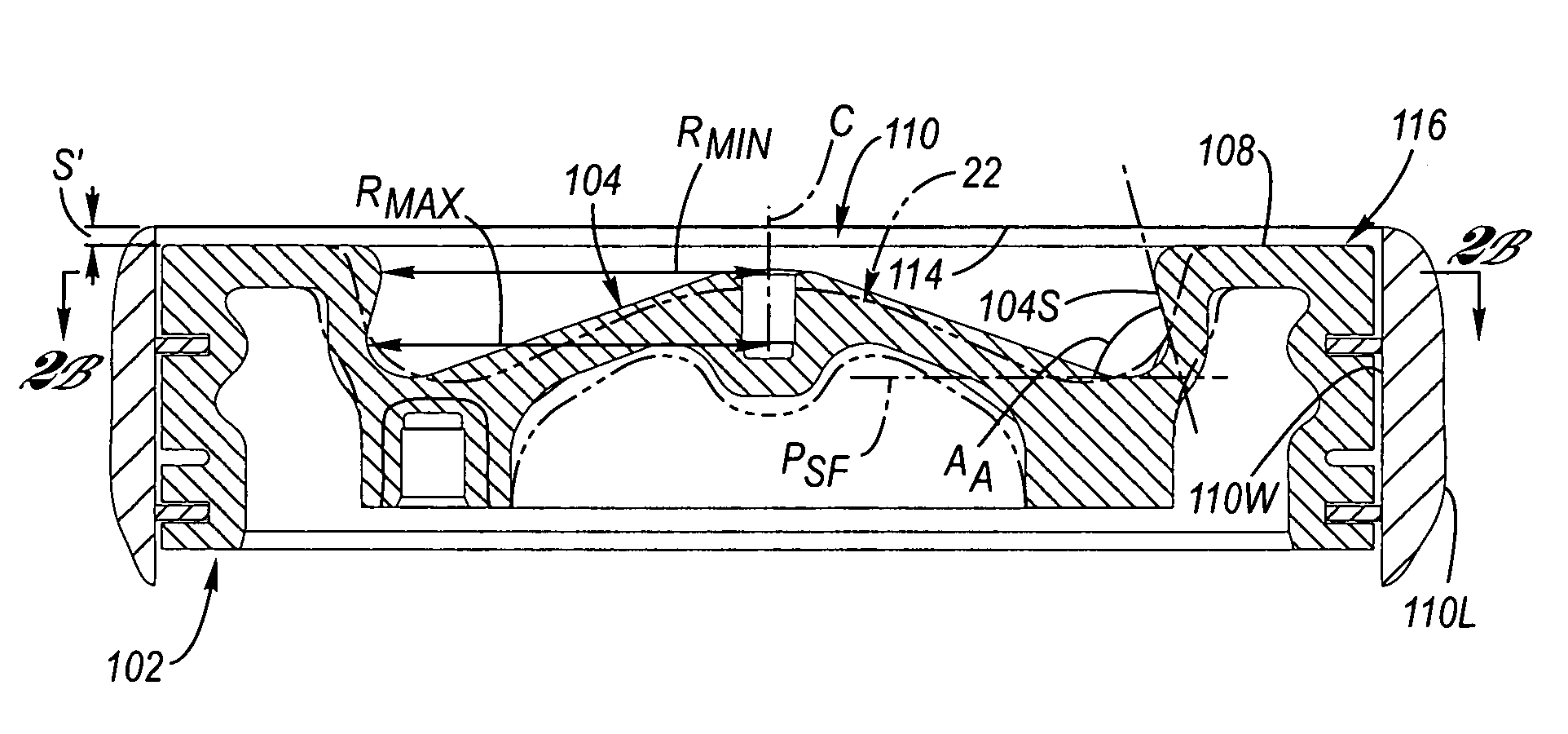
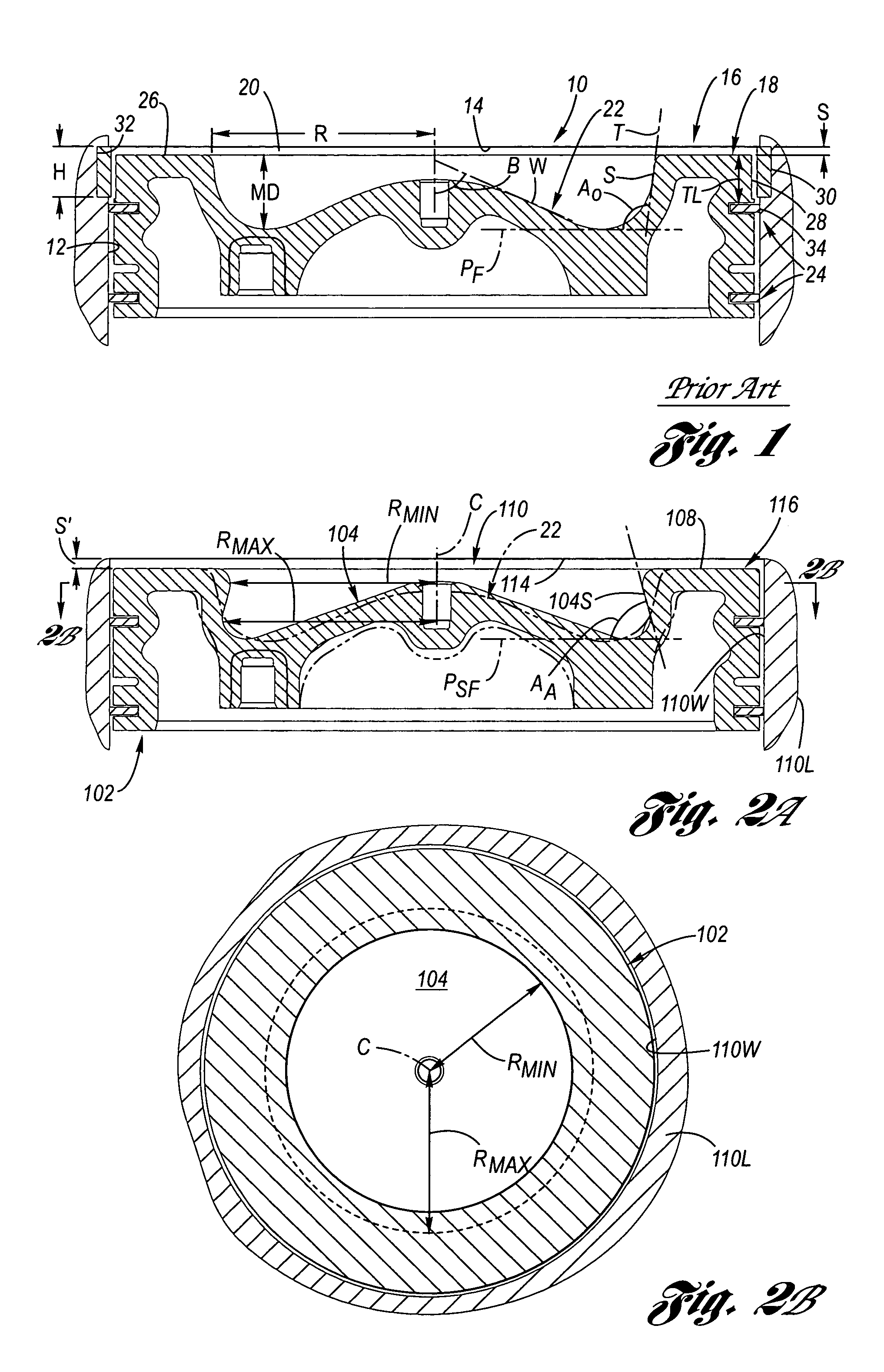
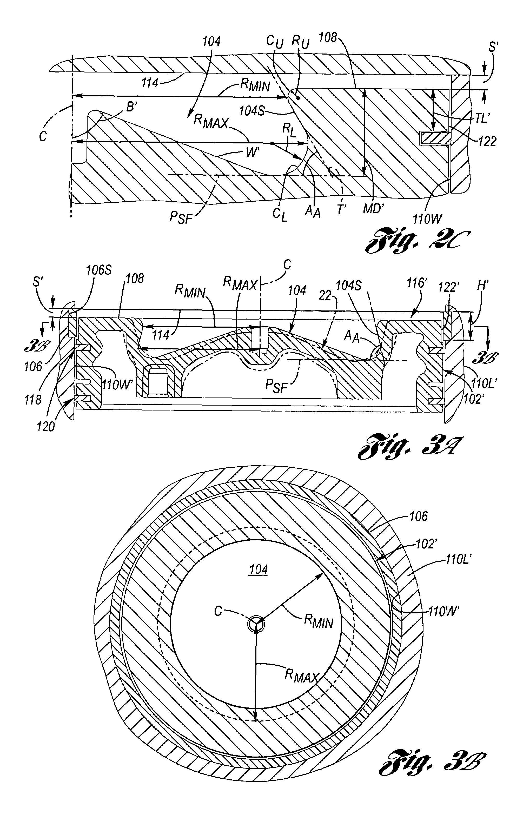
[0039]Referring now to the drawing, FIGS. 2A through 8B depict various aspects of the present invention. In the various views of FIGS. 2A, 3A, 4A, 5, 6 and 7, a large-bore (of at least 180 mm diameter) diesel engine cylinder 100 is shown featuring a piston having an acute re-entrant angle crown bowl, wherein for comparative and referential purposes, the prior art obtuse re-entrant angle crown bowl 22 of FIG. 1 is shown in phantom.

[0040]Referring firstly to FIGS. 2A and 2B, depicted is a large-bore (at least about 180 mm in diameter) diesel engine cylinder 110. The cylinder 110 has a cylinder liner 110L having a cylinder liner wall 110W, and includes thereat a cylinder head 114 and a piston 102 having a piston crown 116, wherein the piston crown has an acute re-entrant angle crown bowl 104. The acute re-entrant angle AA is related to the orientation of the bowl sidewall 104S relative to a squish face plane PSF which is oriented parallel to the squish face 108 of the piston.

[0041]FIG....


PUM


Abstract

A large-bore (at least 180 mm diameter) diesel engine cylinder configuration featuring a piston crown bowl having an acute re-entrant angle and, optionally, an anti-polish ring. The acute re-entrant angle crown bowl involves a maximum radius of the crown bowl exceeding a minimum crown bowl radius, wherein the maximum crown bowl radius is located farther from the squish face than is the minimum crown bowl radius. The acute re-entrant angle crown bowl applied to large-bore, medium-speed diesel engines yields an improvement in performance and emissions characteristics. The anti-polish ring may be integrally formed with the cylinder liner and used in any internal combustion engine.

Description

TECHNICAL FIELD[0001]The present invention relates to diesel engines, and more particularly to diesel engine pistons having a crown bowl. Still more particularly, the present invention relates to a large-bore, medium-speed diesel engine piston crown bowl having an acute re-entrant angle of the bowl sidewall. The present invention further relates to internal combustion engine cylinders having an anti-polish ring.BACKGROUND OF THE INVENTION[0002]In-cylinder emissions reduction techniques have been continuously explored to meet the future regulated exhaust emissions standards for large-bore, medium speed diesel engines typically found in locomotives, marine and industrial co-generation power units.[0003]For convenience, diesel engines are classified into high-speed and medium-speed engines based on engine bore size. Large-bore, medium-speed diesel engines have bore sizes ranging from 180 to 600 mm and small-bore and medium-bore, high-speed diesel engines have bore sizes ranging from 80...

Claims


Application Information

Patent Timeline
Patent Type & Authority Patents(United States)
IPC IPC(8): F02B3/00F02B23/06F02F3/00F02F3/26
CPCF02B23/0672F02B23/0696Y02T10/125Y02T10/12
Inventor POOLA, RAMESH B.GRYFAKIS, NICHOLASACOSTA, GERMAN A.BEASLEY, JOHN L.BLASE, JAMES L.GOETZKE, MICHAEL
Owner ELECTRO-MOTIVE DIESEL
Why Eureka
Try Eureka