

Tangential standing vortex burning chamber
A technology of combustion chamber and vortex, which is applied in the direction of combustion chamber, continuous combustion chamber, combustion method, etc., can solve the problems of poor stability and unsuitable combustion organization, and achieve reduced aerodynamic loss, good local flame stability, and good atomization effect of effect
- Summary
- Abstract
- Description
- Claims
- Application Information
AI Technical Summary
Problems solved by technology
Method used
Image

Examples
Embodiment Construction
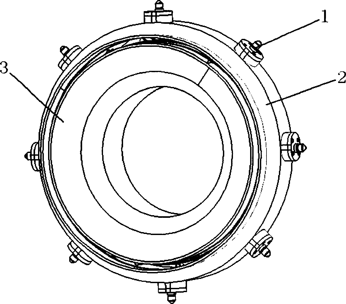
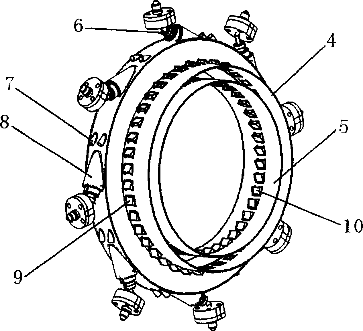
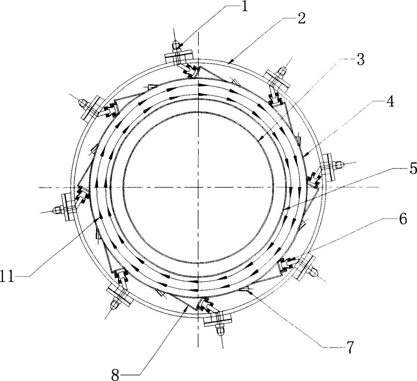
[0028] like figure 1 , 2 , 3, the present invention is mainly composed of an inner casing 3, an outer casing 2, an inner flame cylinder 5 and an outer flame cylinder 4, and the outer flame cylinder 4 is uniformly equipped with a head 1 and a main combustion hole 8 along the circumferential direction, according to The number of oil supply heads is generally between 2 and 20 according to different inlet air volume, swirl degree and structural size requirements. Different nozzles can be used under different oil supply pressures and flow rates. At present, centrifugal nozzles are optional. There are two types of air atomizing nozzles; the main combustion hole 8 is located downstream of the head 1, and the inclination angle between the center line of the head 1 and the main combustion hole 8 and the circumferential tangent is 15°-75°; the head 1 includes the oil supply nozzle 6 and fire stabilizing tube 7; the outer mixing hole 9 and the inner mixing hole 10 are respectively locat...
PUM
 Abstract
Description
Claims
Application Information