Gas turbine movable vane guard ring structure with grate teeth for tight sealing

A gas turbine, grate tooth sealing technology, applied in the direction of machines/engines, mechanical equipment, engine components, etc., can solve the problems of large aerodynamic loss and low performance, achieve good performance, improve performance, and reduce aerodynamic loss Effect

Inactive Publication Date: 2020-03-06
SICHUAN UNIV
View PDF6 Cites 4 Cited by
  • Summary
  • Abstract
  • Description
  • Claims
  • Application Information

AI Technical Summary

Problems solved by technology

[0003] The purpose of the present invention is to provide a gas turbine blade guard ring structure with grating teeth seal to solve the problems of large aerodynamic loss and low service performance of existing gas turbines

Method used


Image

  • Gas turbine movable vane guard ring structure with grate teeth for tight sealing
  • Gas turbine movable vane guard ring structure with grate teeth for tight sealing
  • Gas turbine movable vane guard ring structure with grate teeth for tight sealing

Examples


Embodiment Construction

[0018] The principles and features of the present invention are described below in conjunction with the accompanying drawings, and the examples given are only used to explain the present invention, and are not intended to limit the scope of the present invention.

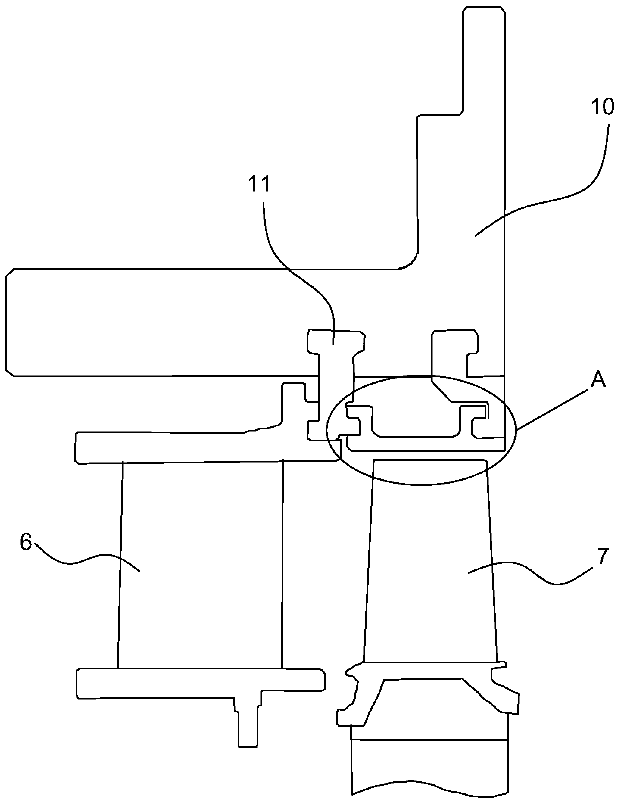
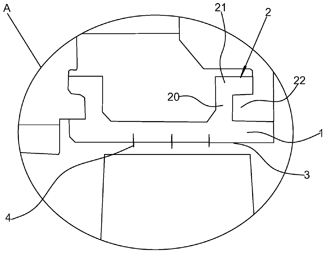
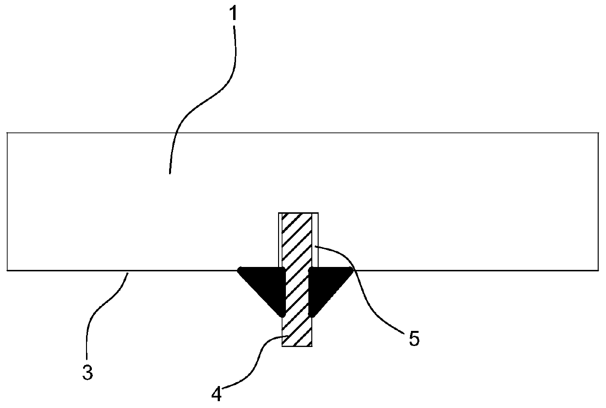
[0019] Such as Figure 1 to Figure 3 As shown, a moving blade guard ring structure of a gas turbine with grating teeth sealing includes a guard ring base 1, hook structures 2 respectively arranged at both ends of the guard ring base 1, and a guard ring profile 3 arranged on the bottom surface of the guard ring base 1 , The profile surface 3 of the retaining ring is provided with a tooth structure.

[0020] The hook structure 2 is used for installation and positioning on the gas turbine cylinder 10 . The guard ring profile 3 corresponds to the rotor blade 7 of the gas turbine, and the setting of the grate tooth structure not only does not change the design of the rotor blade tip of the gas turbine rotor 7, but also ...


PUM


Abstract

The invention discloses a gas turbine movable vane guard ring structure with grate teeth for tight sealing. The gas turbine movable vane guard ring structure comprises a guard ring base body, hook structures arranged at the two ends of the guard ring base body and a guard ring molded surface arranged on the bottom surface of the guard ring base body, and the guard ring molded surface is provided with a grate tooth structure; and the grate tooth structure comprises at least one grate tooth arranged on the guard ring molded surface, the guard ring molded surface is provided with grooves matchedwith the grate teeth, one end of each grate tooth is connected into the corresponding groove in a matched manner, and the other end of each grate tooth and the surface of the guard ring molded surfaceare welded. Cooling air flows out from a guard ring and the upstream adjacent fixed vane end wall, and the cooling air covering and protecting effect is formed on the guard ring molded surface. By means of the guard ring structure, under the condition that an existing movable vane top structure is not changed, the guard ring molded surface is provided with the grate tooth structure, and thereforewhen main flow fuel gas flows through a movable vane top gap, the leakage flow of the main flow fuel gas at the movable vane top gap is reduced, the pneumatic loss of the vane top gap is reduced, andthe performance of a gas turbine is improved.

Description

technical field [0001] The invention relates to the technical field of gas turbines, in particular to a movable blade retaining ring structure with grate seals for gas turbines. Background technique [0002] With the continuous increase of the turbine inlet temperature of the gas turbine, the thermal load environment faced by the turbine blades becomes more severe. In order to ensure a reasonable service life of high temperature turbine blades, it is necessary to cool them effectively. Among them, the cooling form of high-temperature turbine moving blades is the most complicated, and the tip of the blade usually has more film cooling hole structures. On the other hand, in order to avoid scratching between the high-speed rotating blade and the stationary cylinder, there is usually a certain gap at the blade tip of the rotor blade, which causes part of the mainstream gas to flow through the blade tip gap and does not perform work, resulting in a large Aerodynamic loss. At th...

Claims


Application Information

Patent Timeline
Patent Type & Authority Applications(China)
IPC IPC(8): F01D5/18F01D9/02F01D11/00
CPCF01D5/186F01D9/023F01D11/003
Inventor 陈伟罗晓波
Owner SICHUAN UNIV
Why Eureka
Try Eureka