Variable geometry turbine with vortex elimination hole structures in front of movable blades

A technology of variable geometry turbine and moving blades, which is applied in the direction of blade support elements, engine components, machines/engines, etc., can solve the problem of increasing gas turbine compressor surge margin, gas generator residual power, variable geometry turbine efficiency decrease, Problems such as the separation and flow of the pressure surface of the moving blade, to achieve good working characteristics in all working conditions, reduce aerodynamic loss, and reduce the effect of lateral pressure difference

Inactive Publication Date: 2016-06-01
HARBIN ENG UNIV
View PDF8 Cites 6 Cited by
  • Summary
  • Abstract
  • Description
  • Claims
  • Application Information

AI Technical Summary

Problems solved by technology

[0003] In the variable geometry turbine of the prior art, under low operating conditions, the adjustable vane is turned off to reduce the working fluid flow and output power, while the movable vane downstream of the adjustable vane tends to operate at a relatively large positive angle of attack, causing dynamic The front side of the blade suction separates the flow; in the start-up and acceleration conditions, the adjustable vane is opened to increase the surge margin of the gas turbine compressor and the residual power of the gas generator, while the downstream moving vane tends to be at a relatively large negative angle of attack running, resulting in severe separation flow on the pressure surface of the rotor blade
According to the research, the three-dimensional se

Method used


Image

  • Variable geometry turbine with vortex elimination hole structures in front of movable blades
  • Variable geometry turbine with vortex elimination hole structures in front of movable blades
  • Variable geometry turbine with vortex elimination hole structures in front of movable blades

Examples


Embodiment Construction

[0019] The present invention will be further described in detail below in conjunction with the accompanying drawings and specific embodiments.

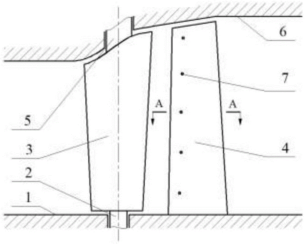
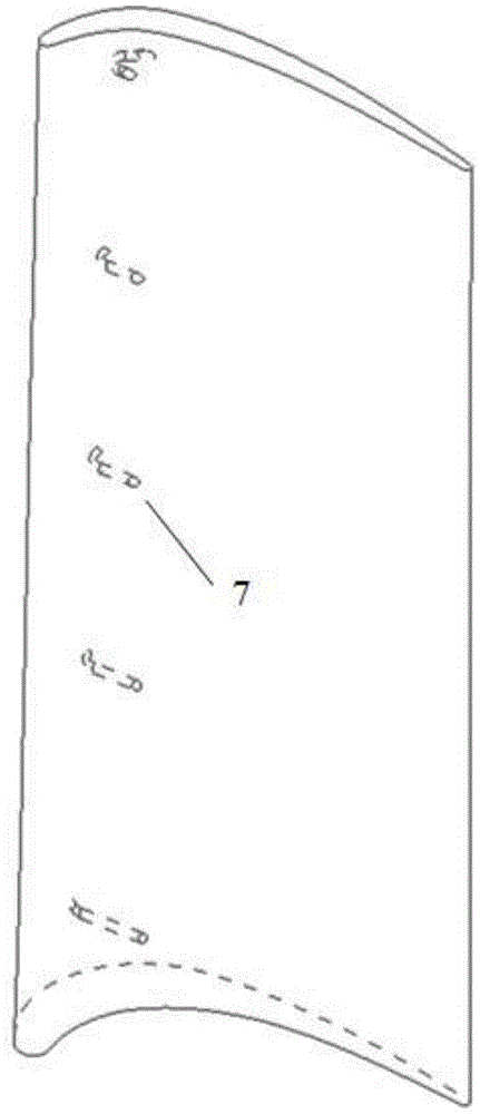
[0020] combine Figure 1~2 , the present invention is made up of wheel hub 1 (comprising stationary blade hub and moving blade hub), adjustable stationary blade 3, moving blade 4 and casing 6, and adjustable stationary blade is evenly installed along the circumferential direction between wheel hub 1 and casing 6 3 and the moving blade 4, the adjustable static blade 3 is in front, and the moving blade 4 is behind. The upper and lower end surfaces of the adjustable stationary blade are respectively provided with an upper rotating shaft 5 and a lower rotating shaft 2, and their axes are on the same rotation axis so that Because the adjustable vane rotates, and the shaft diameter of the upper rotating shaft is larger than that of the lower rotating shaft, the lower rotating shaft only serves as a positioning function, the upper rotating s...


PUM


Abstract

The invention provides a variable geometry turbine with vortex elimination hole structures in the front of movable blades. The variable geometry turbine comprises a case and hubs, wherein adjustable static blades and the movable blades are uniformly installed between the case and the hubs in the circumferential direction, upper rotating shafts and lower rotating shafts are installed on the upper end faces and the lower end faces of the adjustable static blades respectively, the upper rotating shafts are embedded into the case, the lower rotating shafts are embedded into the correspondinghub, the movable blades are installed on the correspondinghub, the curved vortex elimination hole structures communicating with blade pressure surfaces and suction surfaces are formed in the front of the movable blades in the radial direction, and load distribution of blade profiles of the movable blades is of a rear-loading type. According to the variable geometry turbine, separation vortexes in the front of the blades can be reduced or even eliminated underthe off-design condition so that aerodynamic loss in channels of the movable blades can be obviously reduced, transverse differential pressure in front of the blades can be reduced underthe design condition, formation of secondary flow can be delayed, and then loss of the secondary flow can be reduced. The variable geometry turbine hasgood characteristic underall operating conditions on the whole.

Description

technical field [0001] The invention relates to a variable geometry turbine, in particular to a variable geometry turbine with a vortex elimination hole structure at the front of the moving blade. Background technique [0002] Gas turbines often operate at off-design conditions, where turbine efficiency is significantly reduced. The variable geometry turbine technology can effectively adjust and optimize the matching between various components of the gas turbine, and improve the acceleration and deceleration characteristics of the gas turbine and the performance of low working conditions. Adjusting the installation angle of the turbine vane is an effective variable geometry method. [0003] In the variable geometry turbine of the prior art, under low operating conditions, the adjustable vane is turned off to reduce the working fluid flow and output power, while the movable vane downstream of the adjustable vane tends to operate at a relatively large positive angle of attack...

Claims


Application Information

Patent Timeline
IPC IPC(8): F01D5/14
CPCF01D5/141F05D2220/32F05D2240/303
Inventor 高杰郑群董平岳国强刘鹏飞
Owner HARBIN ENG UNIV
Why Eureka
Try Eureka