Detachable cargo hold connecting wing double-fuselage logistics unmanned aerial vehicle

A dual-fuselage, dismantling technology, applied in the direction of equipment, fuselage, full-wing aircraft for loading and unloading goods, etc., can solve the limitations of the popularity of logistics drones, low economy and loading efficiency, and drone payloads. Small and other problems, to achieve the effect of flexible load loading, improve cargo handling efficiency, improve aerodynamic characteristics and structural characteristics

Pending Publication Date: 2019-09-13
ZHENGZHOU UNIVERSITY OF AERONAUTICS
View PDF0 Cites 3 Cited by
  • Summary
  • Abstract
  • Description
  • Claims
  • Application Information

AI Technical Summary

Problems solved by technology

[0003] The technical problem of the present invention lies in the following key problems in the current design of medium and long-range logistics UAVs: (1) The payload of UAVs is small; (2) The adaptability of airports, especially general airports, is poor; (3) Economical and loading efficiency is low
Thus limiting the popularity of logistics drones

Method used


Image

  • Detachable cargo hold connecting wing double-fuselage logistics unmanned aerial vehicle
  • Detachable cargo hold connecting wing double-fuselage logistics unmanned aerial vehicle
  • Detachable cargo hold connecting wing double-fuselage logistics unmanned aerial vehicle

Examples


Embodiment 1

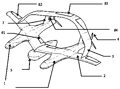
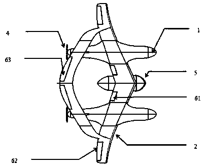
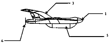
[0025] A detachable logistics UAV with connecting wings and double fuselages of the present invention, the detachable logistics UAV with connecting wings and double fuselages of the cargo compartment includes a wing-body fusion double fuselage 1, a lower main wing 2, Upper auxiliary wing 3, propulsion device 4, modular detachable cargo hold 5, flight control system 6 and vertical tail 7.

[0026] The wing-body fused twin fuselage 1 and the lower main wing 2 adopt a smooth transition on a curved surface, and the lower main wing 2 and the upper auxiliary wing form a connecting wing structure. The wing-body fused twin fuselage 1 is located at the position where the lower main wing 2 is 0.2 times half-span from the wing root.

[0027] The lower main wing 2 adopts a low-speed airfoil with a sweep angle of 10 degrees and a dihedral angle of 0 to 3 degrees to improve flight stability. The upper auxiliary wing 3 is connected to the wing tip position of the lower main wing 2, and is 0...

Embodiment 2

[0034] The difference between embodiment 2 and embodiment 1 is:

[0035] The wing-body fused twin fuselage 1 is located at the position where the lower main wing 2 is 0.3 times half-span from the wing root;

[0036] The lower main wing 2 adopts a low-speed airfoil with a sweep angle of 15 degrees and a dihedral angle of 1 degree;

[0037] Described upper auxiliary wing 3 is connected to the wingtip position of lower main wing 2, and is 0.15 times of half spread length from wing tip, forms the connecting wing structure, and described upper auxiliary wing 3 is low-speed airfoil, and the sweep angle is 25 degree.

[0038] The wing-body fused twin fuselage 1, the lower main wing 2 and the upper auxiliary wing 3 are made of aluminum-magnesium alloy and composite materials.

Embodiment 3

[0040] The wing-body fused twin fuselage 1 is located at the position where the lower main wing 2 is 0.4 times half-span from the wing root;

[0041] The lower main wing 2 adopts a laminar airfoil with a sweep angle of 20 degrees and a dihedral angle of 1 degree;

[0042] The upper auxiliary wing 3 is connected to the wing tip position of the lower main wing 2, and is 0.25 times half-span length from the wing tip to form a connecting wing structure. The upper auxiliary wing 3 is a laminar flow airfoil with a forward sweep angle is 35 degrees.

[0043] The wing-body fused twin fuselage 1, the lower main wing 2 and the upper auxiliary wing 3 are made of aluminum-magnesium alloy and carbon fiber materials.


PUM


Abstract

The invention discloses a detachable cargo hold connecting wing double-fuselage logistics unmanned aerial vehicle. The detachable cargo hold connecting wing double-fuselage logistics unmanned aerial vehicle comprises a wing body fusion type double-fuselage, a lower main wing, an upper auxiliary wing, a propelling device, a modular detachable cargo hold, a flight control system and a vertical tailwing; curved surface smooth transition is adopted between the wing body fusion type double-fuselage and the lower main wing; the lower main wing and the upper auxiliary wing form a connecting wing structure; the modular detachable cargo hold is located in the middle of the lower main wing; and the flight control system comprises a flap located on the inner side of the lower main wing, an auxiliarywing located on the outer side, an elevator located on the upper auxiliary wing and a rudder. The double-fuselage logistics unmanned aerial vehicle disclosed by the invention has the advantages of relatively high loading space, excellent aerodynamic performance, better airport adaptability, excellent economy and relatively high cargo loading efficiency.

Description

technical field [0001] The invention relates to the field of design and manufacture of unmanned aerial vehicles, in particular to a detachable cargo hold connecting wing double-fuselage logistics unmanned aerial vehicle. Background technique [0002] With the rapid development of e-commerce and the regional economy of airports, the logistics industry has become more and more aware of the importance of drones, and has formed a long-distance, medium-distance, medium-distance, short-distance, and terminal logistics system. The terminal and short-distance logistics distribution is generally It can be realized by manned truck express delivery or multi-rotor UAV. Long-distance can be completed by enterprise railway, highway and large-scale passenger-to-cargo manned aircraft. However, for medium-distance and medium-distance logistics transportation, the use of the above methods will increase the cost and urgently need a solution. An air transportation method used for medium-distanc...

Claims


Application Information

Patent Timeline
Patent Type & Authority Applications(China)
IPC IPC(8): B64C39/10B64C3/10B64C1/00B64D9/00B64C5/06B64C9/00
CPCB64C1/00B64C3/10B64C5/06B64C9/00B64C39/10B64C2001/0054B64C2009/005B64D9/00
Inventor 刘战合乔良直田秋丽张芦王晓璐郝爱民苗楠田博韬夏陆林罗丽红张曼王菲
Owner ZHENGZHOU UNIVERSITY OF AERONAUTICS
Why Eureka
Try Eureka