Non-ferromagnetic material irregular crack imaging method based on AC electromagnetic field

An AC electromagnetic field, non-ferromagnetic technology, applied in the direction of material magnetic variables, etc., can solve the problems such as the inability to visually display the surface contour of irregular cracks, the difficulty in realizing irregular cracks, and the inability to realize imaging display of irregular cracks.

Active Publication Date: 2019-09-13
CHINA UNIV OF PETROLEUM (EAST CHINA)
View PDF6 Cites 8 Cited by
  • Summary
  • Abstract
  • Description
  • Claims
  • Application Information

AI Technical Summary

Problems solved by technology

[0003] Among the existing non-destructive testing technologies, magnetic powder and magnetic flux leakage can only be used for defect detection of ferromagnetic materials; ultrasonic is mainly used for internal defect detection; penetration testing needs to remove the coating and thoroughly clean the surface of the structure, and the waste liquid generated during the testing process It can pollute the environment; eddy current detection technology relies on impedance analysis method to realize the imaging display of irregular cracks in any direction
The AC electromagnetic field detection technology has outstanding advantages in the field of crack detection on the surface of conductive materials. At present, the AC electromagnetic field detection technology is judged based on the characteristic signals Bx and Bz or their butterfly diagrams. Among them, the Bx and Bz signals are parallel to the surface of the specimen ( Parallel to the scanning direction of the probe) and the magnetic field signal perpendicular to the surface of the test piece. This characteristic signal can only determine the existence of defects and evaluate the regular cracks. It cannot realize the imaging display of irregular cracks and cannot visually display the irregular cracks. surface profile

Method used


Image

  • Non-ferromagnetic material irregular crack imaging method based on AC electromagnetic field
  • Non-ferromagnetic material irregular crack imaging method based on AC electromagnetic field
  • Non-ferromagnetic material irregular crack imaging method based on AC electromagnetic field

Examples


Embodiment 1

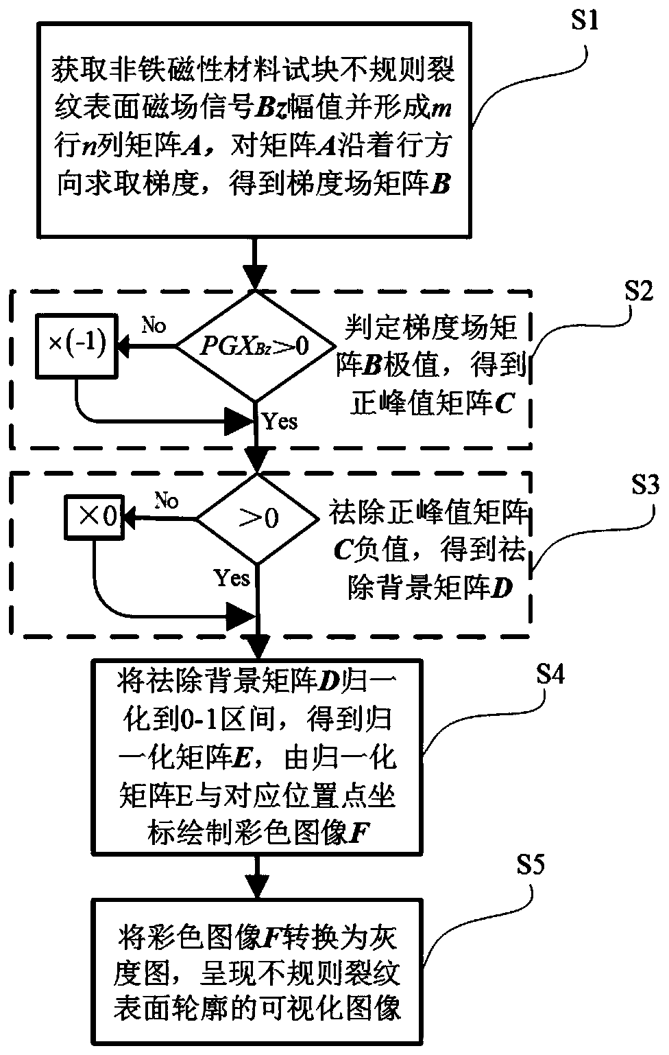
[0024] figure 1 The flow chart of the imaging method for irregular cracks in non-ferromagnetic materials based on AC electromagnetic field detection technology provided by the embodiment of the present invention includes:

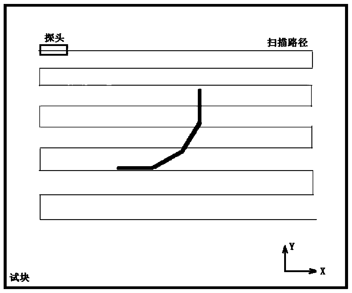
[0025] S1, prepare a stainless steel test block, with irregular cracks on the surface of the test block, such as figure 2 As shown, the irregular crack is 0.5mm wide and consists of four cracks at 0°, 30°, 60° and 90°, each crack is 30.0mm long and 4.0mm deep. Define the probe scanning direction as the X direction, adopt the grid scanning method, and use the AC electromagnetic field detection probe to detect the 48mm×48mm area along the scanning path at the same height plane on the surface of the irregular crack of the test block, such as image 3 shown. The scan step length in the X direction is 2.0mm, the number of equally spaced points on the scan path in the X direction is 25, the distance between the scan paths in the Y direction is 2.0mm, and the n...


PUM


Abstract

The invention discloses a non-ferromagnetic material irregular crack imaging method based on AC electromagnetic field detection, relating to the technical field of nondestructive detection defect imaging. The method comprises steps of acquiring an AC electromagnetic field plane scanning result-a magnetic field signal Bz amplitude matrix by using a grid scanning method, acquiring a gradient field matrix of distorted magnetic field signal Bz maximum distortion value by using a gradient field, so as to reflect aggregation conditions of induced current at irregular crack end points and edges; andfurther, obtaining a surface profile intuitive imaging result of the non-ferromagnetic material irregular crack through resolving of the extreme value, elimination of the background, normalization andgrayscale conversion. The method can assess the non-ferromagnetic material crack visually and predict remaining service life accurately.

Description

technical field [0001] The invention relates to the technical field of non-destructive detection defect imaging, in particular to an imaging method for irregular cracks in non-ferromagnetic materials based on AC electromagnetic field detection technology. Background technique [0002] Non-ferromagnetic conductive materials such as stainless steel and aluminum alloy are widely used in the industrial field. Due to long-term service in corrosive media and complex stress environments, various irregular cracks may occur on the surface of the material, threatening the safe service of the structure. Alternating Current Field Measurement (ACFM) technology is a new electromagnetic non-destructive testing technology, mainly used for crack detection on the surface of conductive materials. It uses the uniform current induced by the detection probe on the surface of the conductive test piece, and the current is generated around the defect. Disturbances cause spatial magnetic field distor...

Claims


Application Information

Patent Timeline
Patent Type & Authority Applications(China)
IPC IPC(8): G01N27/82
CPCG01N27/82
Inventor 袁新安李伟陈国明赵建明蒋维宇张展薛瑞琪
Owner CHINA UNIV OF PETROLEUM (EAST CHINA)
Why Eureka
Try Eureka