
Contactor bounce feature calculation method considering structural thermal field effect

A characteristic calculation, contactor technology, applied in the direction of calculation, instrument, special data processing application, etc., can solve the problem of increased heat generation, complex multi-physics coupling motion state and bounce characteristics of contactors, and no multi-physics involved in the action process. Coupling to solve problems such as dynamic characteristics

Active Publication Date: 2019-09-13
贵州振华群英电器有限公司(国营第八九一厂)
View PDF4 Cites 2 Cited by
  • Summary
  • Abstract
  • Description
  • Claims
  • Application Information

AI Technical Summary

Problems solved by technology

In recent years, the increase in the working power of the contactor itself has led to an increase in the calorific value of its structure, and the calculation error caused by ignoring the temperature has become more and more obvious
The impact and collision problem in the on-off process itself has instantaneous nonlinearity, coupled with the influence of temperature rise changes in the contactor structure, making the multi-physics field coupling motion state and bounce characteristics of the contactor more complicated
[0003] Traditional contactor bounce characteristic analysis or temperature field analysis focuses on electromagnetic-structure, electromagnetic-thermal field coupling research, and does not involve the complex action process and its electric, magnetic, thermal multi-physics field coupling to solve the dynamic characteristics

Method used


Image

  • Contactor bounce feature calculation method considering structural thermal field effect
  • Contactor bounce feature calculation method considering structural thermal field effect
  • Contactor bounce feature calculation method considering structural thermal field effect

Examples


Embodiment

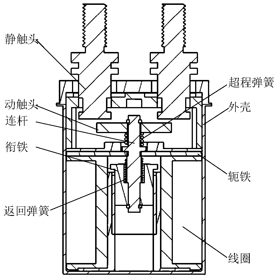
[0133] The structure profile of the contactor is as figure 1 . The relevant parameters of the contactor are: room temperature 20°C, stroke 2.68mm, opening distance 1.7mm, moving contact mass 7g, armature mass 9g, connecting rod mass 4g, coil current 0.7A, coil resistance 40Ω, overtravel spring preload 7N, The stiffness of the overtravel spring is 13N / m, the preload of the return spring is 6N, and the stiffness of the return spring is 0.37N / m.

[0134] The calculation process is as follows:

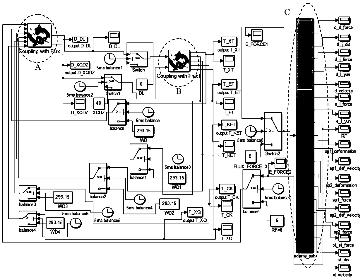
[0135] (1) Establish the thermal field module of the contactor according to the operation steps of the thermal field module, figure 2 A area;

[0136] (2) Establish the electromagnetic module of the contactor according to the operation steps of the electromagnetic module, figure 2 Area B;

[0137] (3) Establish the contactor vibration and collision module according to the operation steps of the vibration and collision module, figure 2 C area;

[0138] (4) According to the operati...


PUM


Abstract

The invention discloses a contactor bounce feature calculation method considering a thermal field effect. The contactor bounce feature calculation method comprises the following steps: firstly, establishing a thermal field mathematical model, an electromagnetic feature mathematical model and a vibration collision mechanical model of a contactor; then establishing a thermal field finite element model, an electromagnetic finite element model and a vibration collision dynamics numerical model of the contactor; naming the thermal field finite element model, the electromagnetic finite element modeland the vibration collision dynamics numerical model of the contactor respectively as a thermal field module, an electromagnetic module and a vibration collision module; carrying out module connection on MATLAB / Simulink according to an action relation data interaction mode among electric-magnetic, electric-magnetic-thermal, and electric-magnetic-structural field; and finally, calculating the bounce feature of the contactor according to an electric-magnetic-thermal-structural multi-physical field model. The contactor bounce feature calculation method has key significance for perfecting the establishment of the contactor bounce model and deeply carrying out multi-physical field coupling calculation and bounce mechanism research on the contactor.

Description

technical field [0001] The invention relates to a method for calculating the bouncing characteristics of a contactor considering the effect of its structural thermal field, in particular to a method for calculating the bouncing characteristics and analyzing the dynamic characteristics of the multi-physics field of electric-magnetism-heat-structure. Background technique [0002] Contactors are often used to control electrical loads and take on important functions such as circuit on-off and voltage release protection. Because the contactor uses a multi-turn coil, and its long-term work will lead to obvious changes in the temperature rise of the structure, which will affect the resistance of the contactor coil and the magnetic saturation of the magnetic material, which will cause changes in the electromagnetic force and seriously affect the contactor. Working status and bounce characteristics. For contactors with no obvious heat generation or whose working temperature is close...

Claims


Application Information

Patent Timeline
IPC IPC(8): G06F17/50
CPCG06F2111/10G06F30/17G06F2119/08G06F30/23G06F2119/06
Inventor 杨文英刘兰香柴玉阳翟国富
Owner 贵州振华群英电器有限公司(国营第八九一厂)
Learn More