Induction motor speed estimation method and power conversion device using same
A technology of power conversion device and induction motor, which is applied in the control of electromechanical transmission device, motor control, motor generator control, etc., can solve the problems of inability to perform stable speed control, insufficient torque, etc., achieve high-precision speed control characteristics, prevent Effects of insufficient torque
- Summary
- Abstract
- Description
- Claims
- Application Information
AI Technical Summary
Problems solved by technology
Method used
Image

Examples
Embodiment 1
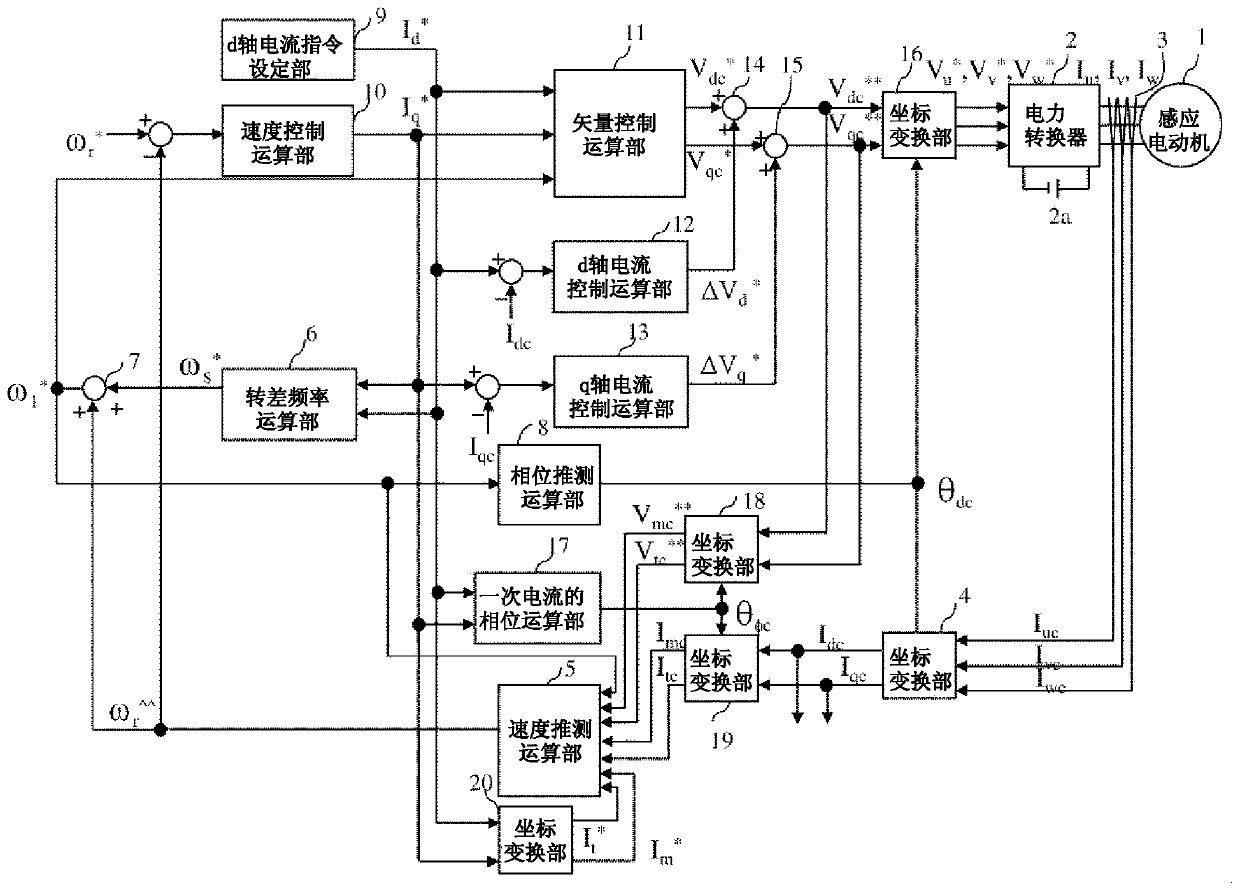
[0031] figure 1 is a configuration diagram of the power conversion device in this embodiment. figure 1 In the induction motor 1 driven by the power conversion device, the magnetic flux generated by the current of the magnetic flux axis component (d axis) and the current of the torque axis direction (q axis) orthogonal to the magnetic flux axis are generated. torque. Power converter 2 outputs and three-phase AC voltage command value V u * , V v * , V w * In direct proportion to the voltage value, the output voltage and output frequency of the induction motor 1 are adjusted. The DC power supply 2 a supplies a DC voltage to the power converter 2 . The current detector 3 outputs the three-phase AC current I of the induction motor 1 u , I v , I w The detection value of I uc , I vc , I wc . The current detector 3 can also detect phase currents of two of the three phases of the induction motor 1, such as the U phase and the W phase, depending on the AC condition (I u ...
Embodiment 2
[0118] In the first embodiment, the accuracy of the speed estimation value is improved in the low-speed section, but in the present embodiment, the method of improving the accuracy of the speed estimation value in the medium-high speed section will be described.
[0119] The structural diagram of the power conversion device in this embodiment is in figure 1 Since the structure is the same except for the speed estimation calculation unit 5, the drawings and descriptions thereof are omitted.
[0120] The speed estimation operation part 5' in this embodiment estimates the back electromotive force value of the t-axis according to formula (20), and outputs ω by dividing by the magnetic flux coefficient r ^^^ .
[0121] [mathematical formula 20]
[0122]
[0123] The voltage component ω included in the numerator term of formula (20) in the middle and high speed range 1 * L σ * I m * because I m * = 0, so even if L σ * There is an error in the setting of , and it is a...
Embodiment 3
[0128] In the first embodiment, the accuracy of the speed estimation value is improved in the low-speed section, but in this example, the method of switching the speed estimation value between the low-speed section and the medium-high speed section will be described.
[0129] The structural diagram of the power conversion device in this embodiment is in figure 1 Since it has the same structure except for the speed estimation calculation unit 5, its drawings and descriptions are omitted.
[0130] exist Figure 7 The structure of the speed estimation operation part 5'' in this embodiment is shown in . The speed estimation operation part 5''a is a calculation part of equation (16), and outputs the speed estimation value ω r ^^ , 5''b is the calculation part of formula (20), and the output speed estimation value ω r ^^^ . 5''c is the switching part of the speed estimation value, and the speed estimation value ω is selected in the low speed section r ^^ , select the speed e...
PUM
 Abstract
Description
Claims
Application Information
 - R&D
- Intellectual Property
- Life Sciences
- Materials
- Tech Scout
- Unparalleled Data Quality
- Higher Quality Content
- 60% Fewer Hallucinations
Browse by: Latest US Patents, China's latest patents, Technical Efficacy Thesaurus, Application Domain, Technology Topic, Popular Technical Reports.
© 2025 PatSnap. All rights reserved.Legal|Privacy policy|Modern Slavery Act Transparency Statement|Sitemap|About US| Contact US: help@patsnap.com