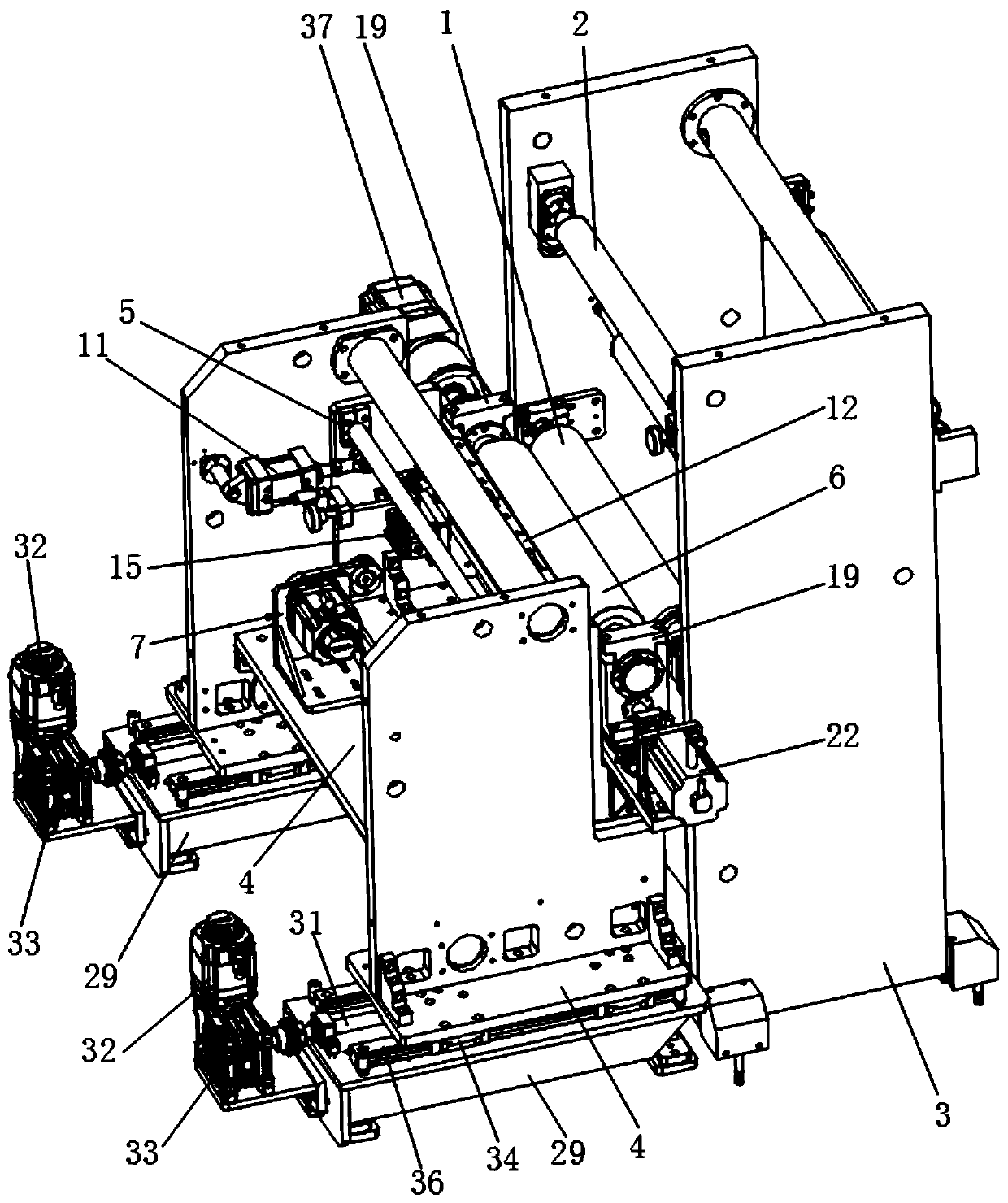
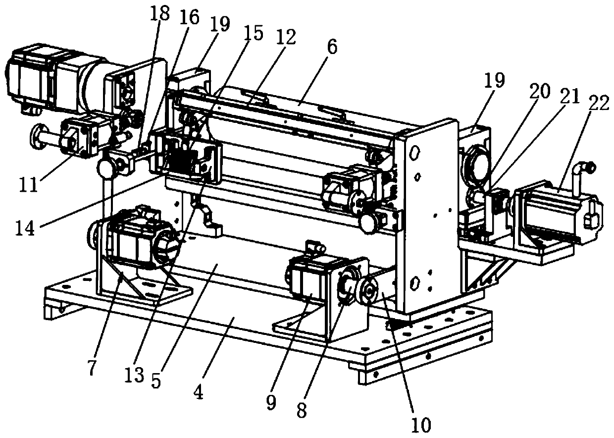
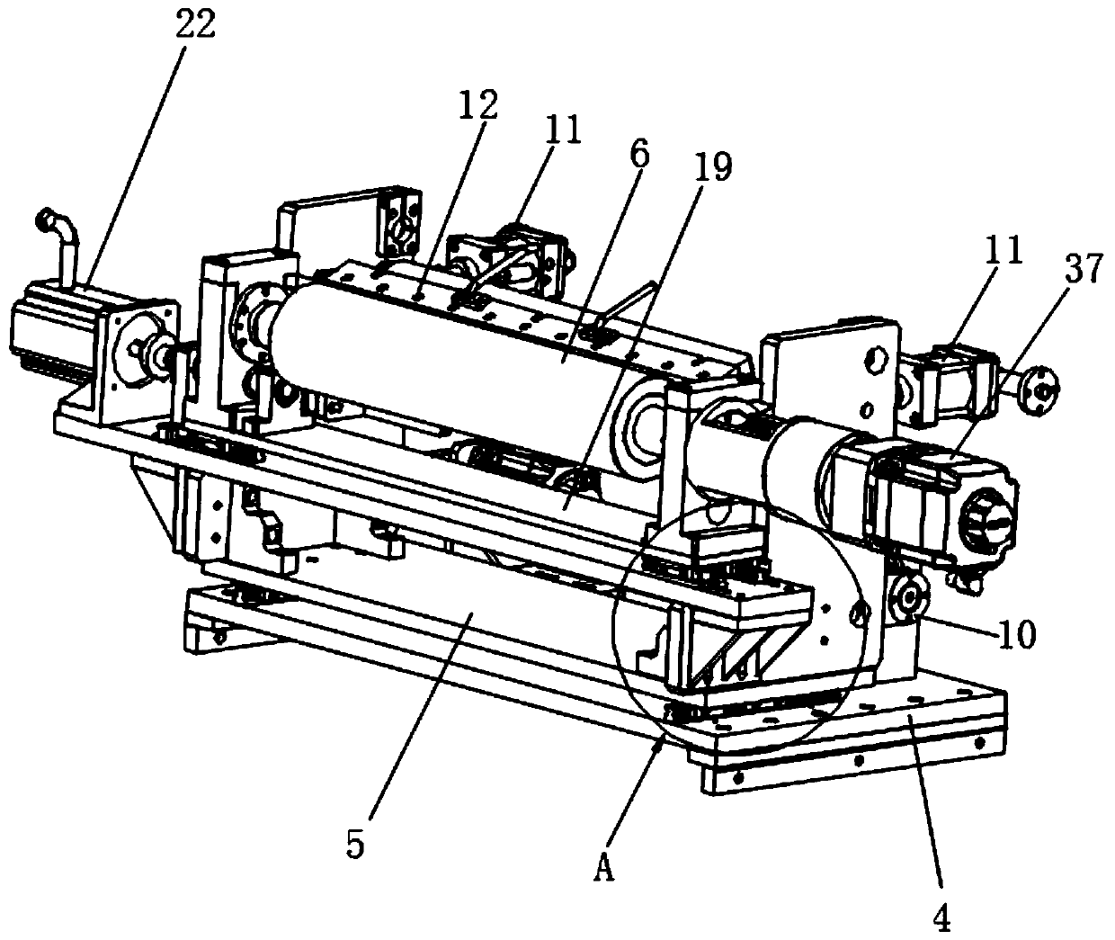
Plate roller movement intermittent coating mechanism

A plate roller and coating technology, which is applied in the field of coating machines, can solve the problems of low coating speed, weak coating precision control, and the length cannot meet the precision requirements, so as to reduce the defective rate, improve coating efficiency, The effect of high coating accuracy

Pending Publication Date: 2019-09-17
SHENZHEN NEW KATOP AUTOMATION TECH
View PDF6 Cites 8 Cited by
  • Summary
  • Abstract
  • Description
  • Claims
  • Application Information

AI Technical Summary

Problems solved by technology

[0003] In the actual coating process, it is sometimes necessary to carry out interval coating on the substrate to be coated. The traditional coating machine for interval coating uses a motor to control the screw to drive the movement of the plate roller with the adhesive on the surface. , make the plate roller close to or away from the rubber roller, and then achieve the purpose of interval coating the substrate on the rubber roller, but there are the following problems when using this kind of coating machine for coating, the surface of the substrate after coating The length of the coated area and the length of the uncoated area cannot meet the ideal precision requirements, the control of coating accuracy is weak, the coating speed is low, and the mechanical wear is fast, etc.
[0004] With the development of the power battery industry, customers have higher and higher requirements for the coating speed and coating accuracy of the coating machine, while the coating speed and coating accuracy of the traditional coating machine for interval coating can no longer meet the demand

Method used


Image

  • Plate roller movement intermittent coating mechanism
  • Plate roller movement intermittent coating mechanism
  • Plate roller movement intermittent coating mechanism

Examples


Embodiment Construction

[0027] The idea, specific structure and technical effects of the present invention will be clearly and completely described below in conjunction with the embodiments and accompanying drawings, so as to fully understand the purpose, features and effects of the present invention. Apparently, the described embodiments are only some of the embodiments of the present invention, rather than all of them. Based on the embodiments of the present invention, other embodiments obtained by those skilled in the art without creative efforts belong to The protection scope of the present invention. In addition, all the connection / connection relationships involved in the patent do not simply refer to the direct connection of components, but mean that a better connection structure can be formed by adding or reducing connection accessories according to specific implementation conditions. The various technical features in the invention can be combined interactively on the premise of not conflictin...


PUM


Abstract

The invention relates to the technical field of coating machines, in particular to a plate roller movement intermittent coating mechanism. The plate roller movement intermittent coating mechanism comprises a coating device for coating the surface of a substrate with an adhesive and a conveying device for conveying the substrate to the coating device. The conveying device comprises a rotationally-arranged rubber roller and a plurality of conveying rollers, the coating device comprises a base, a connecting seat arranged on the base in a sliding manner, a plate roller rotationally arranged on the connecting seat and a first driving assembly used for driving the connecting seat to move in the direction getting close to or being away from the rubber roller, the plate roller is arranged on the side close to the rubber roller, the first driving assembly comprises a cam, a first driving member for driving the cam to rotate and a connecting rod eccentrically connected to the side, far away from the first driving member, of the cam, the connecting rod is rotatably connected with the cam, and the end, far away from the cam, of the connecting rod is rotatably connected with the connecting seat. The plate roller movement intermittent coating mechanism has the advantages of high coating accuracy and high coating speed.

Description

technical field [0001] The invention relates to the technical field of coating machines, in particular to a moving discontinuous coating mechanism for plate rollers. Background technique [0002] The coating machine is mainly used for the production of surface coating process of film, paper, etc. It is to coat the rolled base material with a layer of special functional adhesive, such as glue, paint or ink, etc., and wind it up after drying. [0003] In the actual coating process, it is sometimes necessary to carry out interval coating on the substrate to be coated. The traditional coating machine for interval coating uses a motor to control the screw to drive the movement of the roller with the adhesive on the surface. , make the plate roller close to or away from the rubber roller, and then achieve the purpose of interval coating the substrate on the rubber roller, but there are the following problems when using this kind of coating machine for coating, the surface of the s...

Claims


Application Information

Patent Timeline
Patent Type & Authority Applications(China)
IPC IPC(8): B05C1/12B05C1/08B05C1/16B05C13/02
CPCB05C1/12B05C1/0813B05C1/0821B05C1/165B05C13/02
Inventor 施伟喻薛刚李宗涛
Owner SHENZHEN NEW KATOP AUTOMATION TECH
Why Eureka
Try Eureka