Stamping machining equipment

A technology of mechanical processing and equipment, which is applied in the field of stamping mechanical processing equipment, can solve the problems of easy bonding of stamping plates, unstable clamping of stamping plates, and affecting production and processing efficiency, so as to improve stamping quality and avoid bonded stamping board, structure simple effect

Active Publication Date: 2019-09-17
苏州茂速拓机械科技有限公司
View PDF7 Cites 20 Cited by
  • Summary
  • Abstract
  • Description
  • Claims
  • Application Information

AI Technical Summary

Problems solved by technology

[0004] The purpose of the present invention is to solve the problem of unstable clamping of the stamping plate in the prior art, which is prone to offset, which affects the quality of stamping, and after the stamping is completed, the stamping plate is easily bonded to the stamping block, and it is necessary to manually assist the stamping plate to detach. Time-consuming and labor-intensive, the shortcomings of affecting the efficiency of production and processing, and a kind of stamping machining equipment proposed

Method used


Image

  • Stamping machining equipment
  • Stamping machining equipment
  • Stamping machining equipment

Examples


Embodiment 1

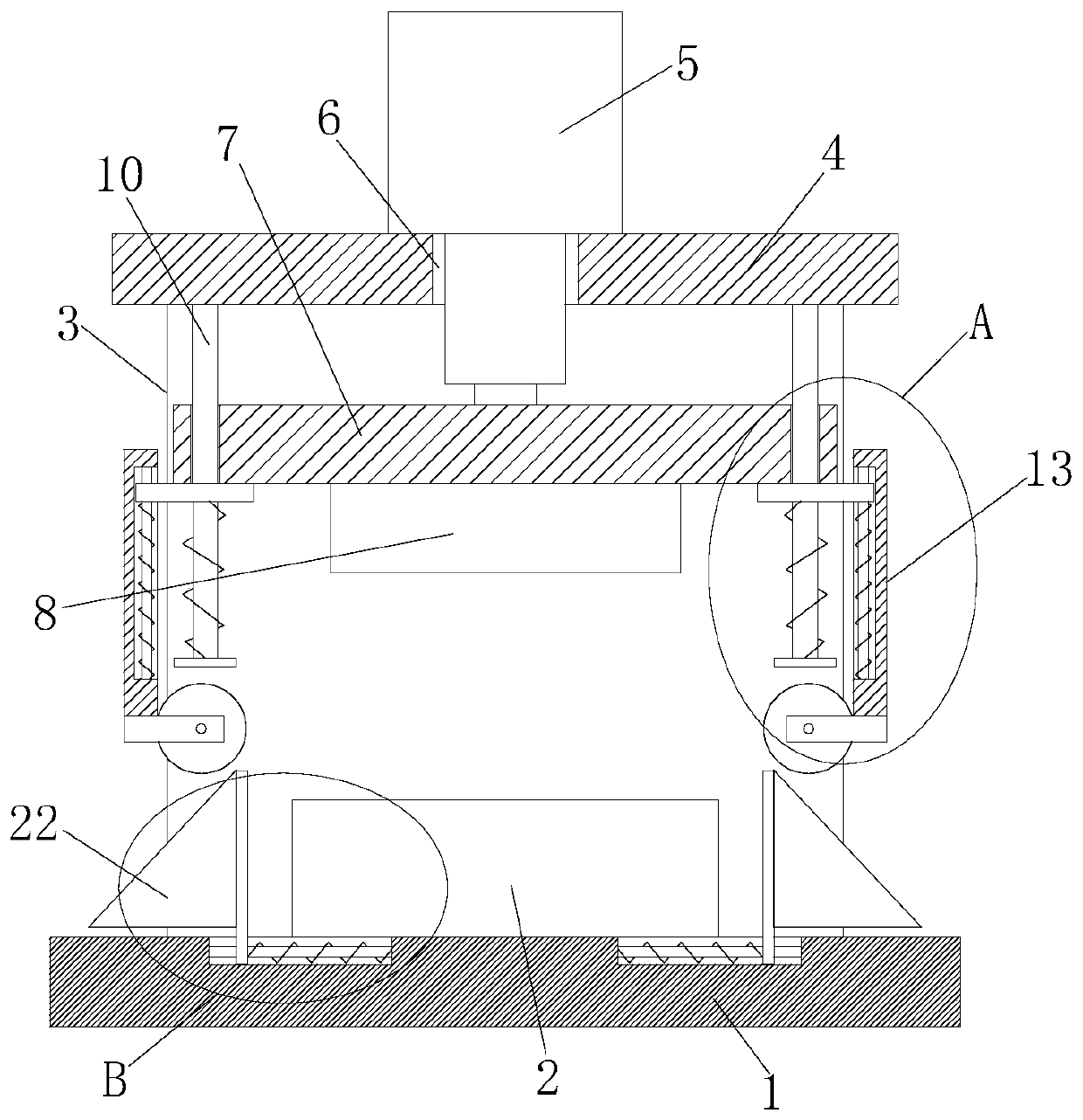
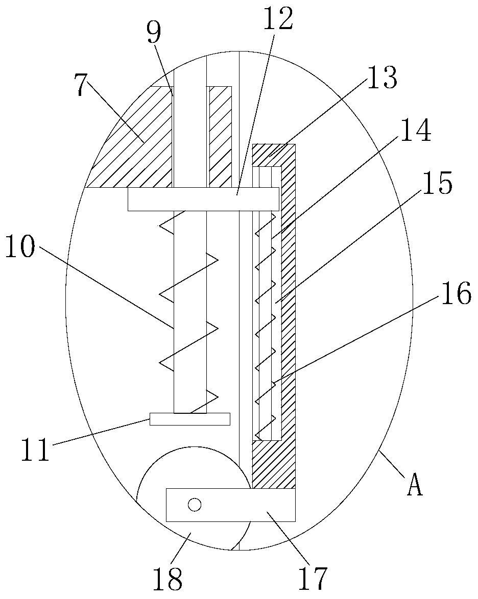
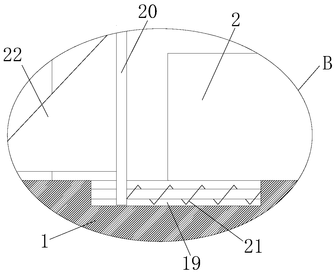
[0026] refer to Figure 1-6, a stamping machine processing equipment, including a processing table 1, the top of the processing table 1 is provided with a stamping plate 2, the top of the processing table 1 is fixedly installed with two fixed plates 3, and the tops of the two fixed plates 3 are fixedly installed with the same Top plate 4, a hydraulic cylinder 5 is fixedly installed on the top of the top plate 4, a through hole 6 is opened on the top plate 4, the piston rod of the hydraulic cylinder 5 extends through the through hole 6 to the bottom of the top plate 4 and a lifting plate 7 is fixedly installed, and the lifting plate 7 The bottom of the top plate 4 is fixedly equipped with a pressing block 8, the lifting plate 7 is located between the two fixed plates 3, the pressing block 8 is located above the punching plate 2, and the bottom of the top plate 4 is fixedly equipped with two fixed rods 10, and the lifting plate 7 is provided with Two lifting holes 9, two fixing ...

Embodiment 2

[0035] refer to Figure 1-6 , a stamping machine processing equipment, comprising a processing table 1, the top of the processing table 1 is provided with a stamping plate 2, the top of the processing table 1 is fixedly installed with two fixing plates 3 by welding, and the tops of the two fixing plates 3 are fixed by welding The same top plate 4 is installed, and the top of the top plate 4 is fixedly installed with a hydraulic cylinder 5 by welding, and a through hole 6 is opened on the top plate 4, and the piston rod of the hydraulic cylinder 5 extends through the through hole 6 to the bottom of the top plate 4 and is fixed and installed by welding Lifting plate 7 is arranged, and the bottom of lifting plate 7 is fixedly installed with briquetting 8 by welding, and lifting plate 7 is positioned between two fixed plates 3, and briquetting block 8 is positioned at the top of stamping plate 2, and the bottom of top plate 4 is fixedly installed with Two fixing rods 10, two lifti...


PUM


Abstract

The invention belongs to the technical field of machining, particularly relates to stamping machining equipment, and aims to solve the problems that the stamping quality is affected by unstable clamping and easy offset of an existing stamping plate, the stamping plate easily adheres to a pressing block after the stamping is completed, and time and labor are wasted to separate the stamping plate. According to the scheme, the stamping machining equipment comprises a machining table, wherein the stamping plate is arranged at the top of the machining table, the top of the machining table is fixedly provided with two fixing plates, the tops of the two fixing plates are fixedly provided with a same top plate, a hydraulic cylinder is fixedly arranged at the top of the top plate, a through hole is formed in the top plate, a piston rod of the hydraulic cylinder penetrates through the through hole to extend below the top plate and is fixedly provided with a lifting plate, and a pressing block is fixedly arranged at the bottom of the lifting plate. The stamping machining equipment is simple in structure, the stamping plate can be clamped, the problem of offset of the stamping plate is avoided, the stamping quality of the stamping plate is improved, and meanwhile, the stamping plate and the pressing block can be conveniently separated, and the problem that the pressing block adheres to the stamping plate is solved.

Description

technical field [0001] The invention relates to the technical field of mechanical processing, in particular to stamping mechanical processing equipment. Background technique [0002] With the rapid development of society, people's demand for mechanical processing equipment is increasing. With the popularization of mechanical processing equipment, not only the labor intensity of people is reduced, but also the production efficiency is improved. Stamping machine is one of the very important ones. Mechanical processing equipment, stamping machines have good performance in processing one-time formed workpieces. [0003] When the existing punching machine is in use, the clamping of the punching plate is unstable, and it is easy to shift, which affects the quality of punching. After the stamping is completed, the punching plate is easy to stick to the punching block, and it is necessary to manually assist the punching plate to detach, which is time-consuming and laborious. , A pr...

Claims


Application Information

Patent Timeline
Patent Type & Authority Applications(China)
IPC IPC(8): B21D37/04B21D22/02B30B1/32
CPCB21D22/02B21D37/04B30B1/32
Inventor 王小珍
Owner 苏州茂速拓机械科技有限公司
Why Eureka
Try Eureka