Feeding-discharging device
A lifting device and conveying device technology, which is applied in the direction of transportation and packaging, conveyor objects, etc., can solve the problems of high production cost, low efficiency, and high labor intensity, and achieve the effects of improving efficiency, reducing manual operations, and improving production efficiency
- Summary
- Abstract
- Description
- Claims
- Application Information
AI Technical Summary
Problems solved by technology
Method used
Image

Examples
Embodiment 1
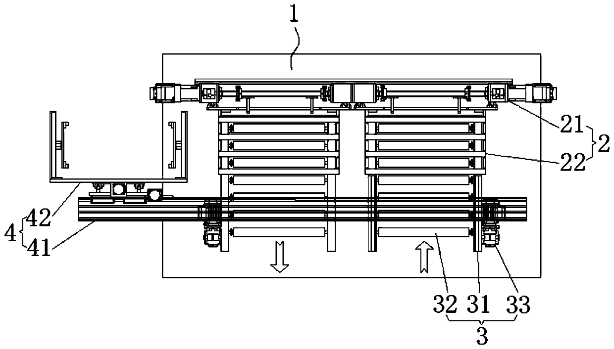
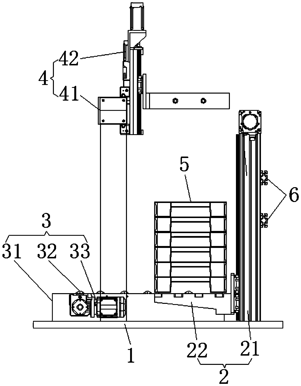
[0035] refer to Figure 1 to Figure 2 , this embodiment discloses a loading and unloading device, including a base 1, a material frame lifting device 2, a conveying device 3 and a transfer device 4; the material frame lifting device 2 is symmetrically fixed on the base 1, and the material frame lifting device The lower part of the device 2 is provided with a conveying device 3 for conveying the material frame 5, and the transfer device 4 is arranged above the material frame lifting device 2, and the conveying device 3 and the transfer device 4 are fixed on the base 1; In this embodiment, the material frame lifting device 2 and the conveying device 3 at the right end of the base 1 are used for loading materials, and the material frame lifting device 2 and the conveying device 3 at the left end of the base 1 are used for unloading; The device 3 cooperates with the setting to realize the mechanical automatic loading and unloading of the material frame 5 for stacking pistons. At t...
Embodiment 2
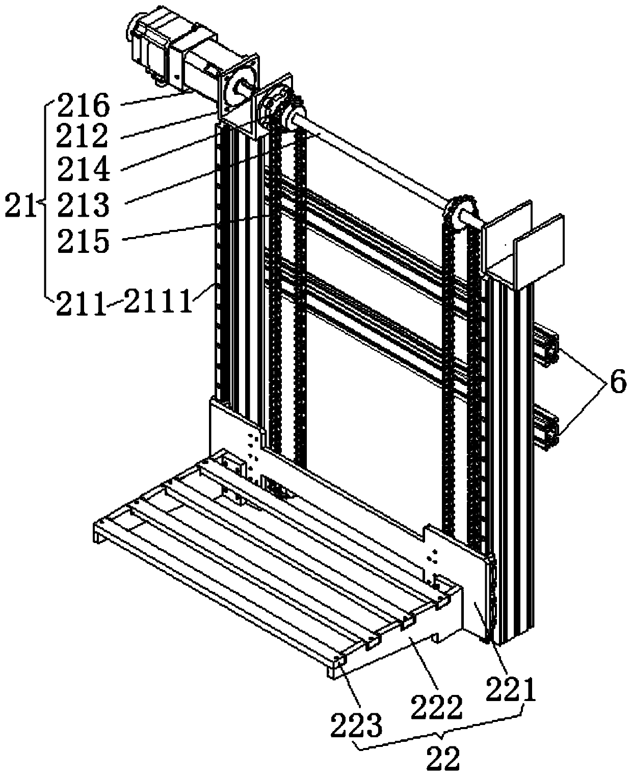
[0047] refer to Figure 8 to Figure 9 The difference between the second embodiment and the first embodiment is that at least one first positioning rod 311 is vertically fixed on the bearing frame 31 arranged at the lower end of the bracket 22, and there are four first positioning rods 311 in this embodiment. , two pairs are distributed on the bearing frame 31, the first positioning rods 311 pass through the gap between the support bars 223, the inner side of the support frame 222 is provided with a chute block 224 that matches the first positioning rods 311, The up and down movement of the bracket 22 is convenient and the friction force is reduced.
[0048] Between the first brackets 211, there is also a parallel horizontal bar (not marked in the figure) passing through the chain. Both ends of the horizontal bar are provided with limit bars 2112. The rods 2112 move up and down, and the first sliding seat 221 is limited by the limiting rod 2112. When the first sliding seat 221...
Embodiment 3
[0051] refer to Figure 10 to Figure 12 The difference between the third embodiment and the second embodiment is that the transfer device 4 also includes a pressing mechanism 43, and the pressing mechanism 43 is fixed on the horizontal slide of the second bracket 41 corresponding to the material frame lifting device 2. On the lower surface of frame 411, the quantity of the pressing mechanism 43 is the same as that of the material frame lifting device 2; the material frame 5 on the bracket 22 is positioned on four sides by the pressing mechanism 43, so as to better prevent the material frame 5 from shifting and improve Productivity.
[0052] The pressing mechanism 43 includes a suspension 431, a pressing cylinder 432 and a pressing plate 433, and the suspension 431 is fixed on the lower surface of the horizontal carriage 411 of the second support 41 corresponding to the material frame lifting device 2. A compression cylinder 432 is fixed on the suspension 431, and the output e...
PUM
 Abstract
Description
Claims
Application Information
PatSnap Eureka turns technology decisions into work you can execute. Powered by our Innovation Knowledge Graph, it runs expert workflows across engineering, life sciences, materials and intellectual property. Get your review-ready output in minutes.


