

Module transfer mechanism, valve tower module replacement device and valve tower module replacement method
A module and valve tower technology, applied in the directions of transportation and packaging, load hanging components, etc., to achieve the effect of high operating efficiency, improving stability and improving efficiency
- Summary
- Abstract
- Description
- Claims
- Application Information
AI Technical Summary
Problems solved by technology
Method used
Image

Examples
Embodiment 1
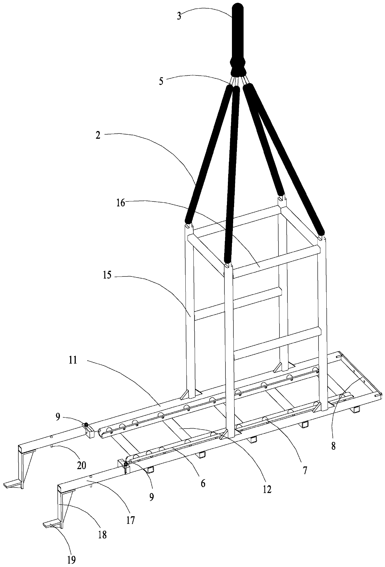
[0050] see Figure 1 to Figure 8 As shown, the present embodiment provides a module transfer mechanism, including: a valve tower module support transfer unit, and a stay rope suitable for lifting the valve tower module support transfer unit from the top of the valve tower module support transfer unit unit.
[0051] The valve tower module support transfer unit includes a bottom support frame suitable for supporting the valve tower module from the bottom of the valve tower module, and an outer frame vertically fixed to the bottom support frame; between the outer frame and the bottom support frame is formed a suitable Containment compartment 1 that accommodates the valve tower module;
[0052] The stay rope unit includes at least four suspension ropes 2 connected to the top of the outer frame away from the bottom support frame, and a total rope 3 connected to at least four suspension ropes 2 at the same time. This embodiment only takes four hanging ropes 2 as an example in conj...
Embodiment 2
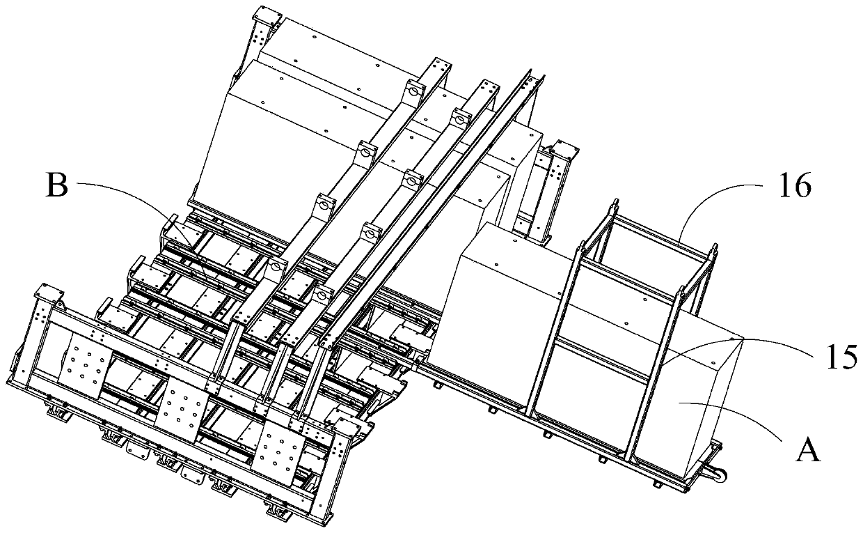
[0061] see Figure 1 to Figure 8 As shown, on the basis of the module transfer mechanism in Embodiment 1, this embodiment provides a valve tower module replacement device, including: the module transfer mechanism in Embodiment 1, and the bottom of the module transfer mechanism The supporting frame faces the side of the valve tower and is suitable for positioning and connecting units overlapped with the valve tower.
[0062] Specifically, the positioning connection unit includes a pair of extension rods 17 extending along the length direction of the bottom support frame and integrally fixed with the bottom support frame, and an L-shaped folded plate formed by bending and connecting with the pair of extension rods 17; A pair of extension rods 17 is adapted to be carried on the side end surface of the bottom support beam 30 for supporting the valve module on the valve tower facing the valve tower module.
[0063] The L-shaped flap includes a first flap 18 vertically connected to...
Embodiment 3
[0072] On the basis of Embodiment 1 and Embodiment, this embodiment provides a valve tower module replacement method, including:
[0073] Step S1: Disconnect the power supply of the valve hall of the valve tower, turn off the water cooling system; then use a tester to test the capacitor voltage to ensure that it has been completely discharged; then remove the interference structural parts of the valve tower module to be replaced; here The interference structure specifically includes a pressure equalizing cover, a pressure equalizing ring, connecting copper bars and diagonal tie rods, etc. A series of operations in this step are realized by the operator using the climbing vehicle to perform manual operations.
[0074]Step S2: Remove the water inlet and outlet pipes of the valve tower module; open the ball valve and exhaust valve at the top of the valve tower, the water inlet pipe drain valve at the bottom of the valve tower, remove the water inlet pipe of the module and install...
PUM
 Abstract
Description
Claims
Application Information