
Colum angle formwork suitable for fabricated building and construction method of column angle formwork

A prefabricated, formwork technology, which is applied in the fields of formwork/formwork/work frame, on-site preparation of building components, and construction, can solve the problems of increased formwork cost, formwork waste, poor pouring quality, etc., to ensure the pouring quality, The effect of ensuring fixed effect and speeding up installation efficiency

Pending Publication Date: 2019-09-17
NINGBO PRECA CONSTR TECH CO LTD
View PDF8 Cites 3 Cited by
  • Summary
  • Abstract
  • Description
  • Claims
  • Application Information

AI Technical Summary

Problems solved by technology

[0003] The traditional joint formwork usually uses wooden formwork for fixed splicing, and then concrete is poured. Because the strength of the wooden formwork is not high, it is easy to bend and deform, and it is prone to moisture expansion and cracking in rainy days. As a result, the wooden formwork cannot be recycled many times. The recycling rate of the formwork is low, and the formwork is seriously wasted; at the same time, the wooden formwork is not firmly fixed, which often causes the concrete to leak, resulting in poor pouring quality
[0004] If metal formwork is used, such as steel formwork, aluminum alloy formwork, etc., it is usually customized according to the node structure of the project building, especially when there are special-shaped columns such as pentagons, hexagons, and curved sides in the construction project, these special-shaped columns There are acute angles, obtuse angles or curved edges in the corners of the columns, and it is difficult to install the formwork in ordinary ways
If it is customized, it will greatly increase the cost of the formwork, and the customized formwork can only be applied to the current project and cannot be recycled, which will greatly increase the construction cost

Method used


Image

  • Colum angle formwork suitable for fabricated building and construction method of column angle formwork
  • Colum angle formwork suitable for fabricated building and construction method of column angle formwork
  • Colum angle formwork suitable for fabricated building and construction method of column angle formwork

Examples


Embodiment Construction

[0027] The present invention will be further described below in conjunction with the drawings and specific embodiments.

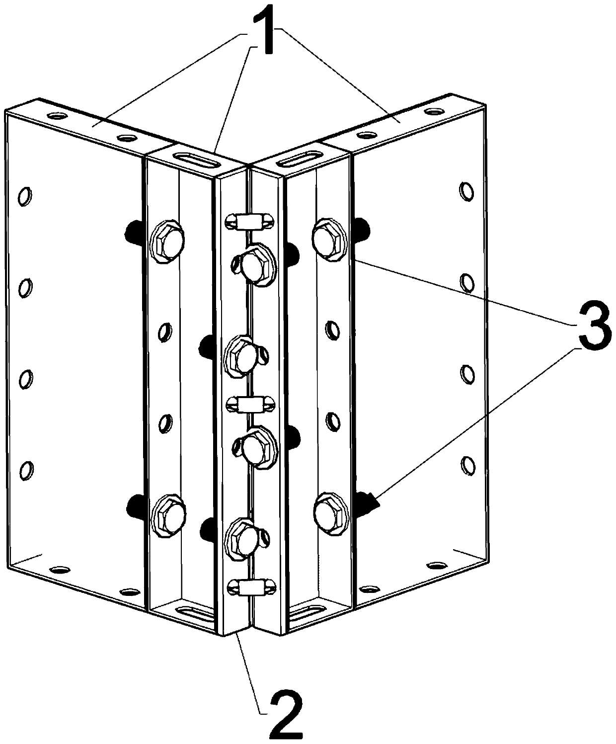
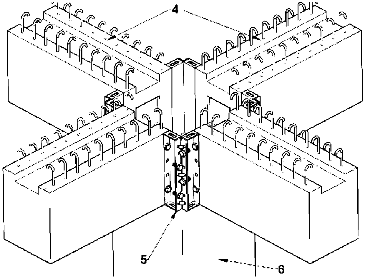
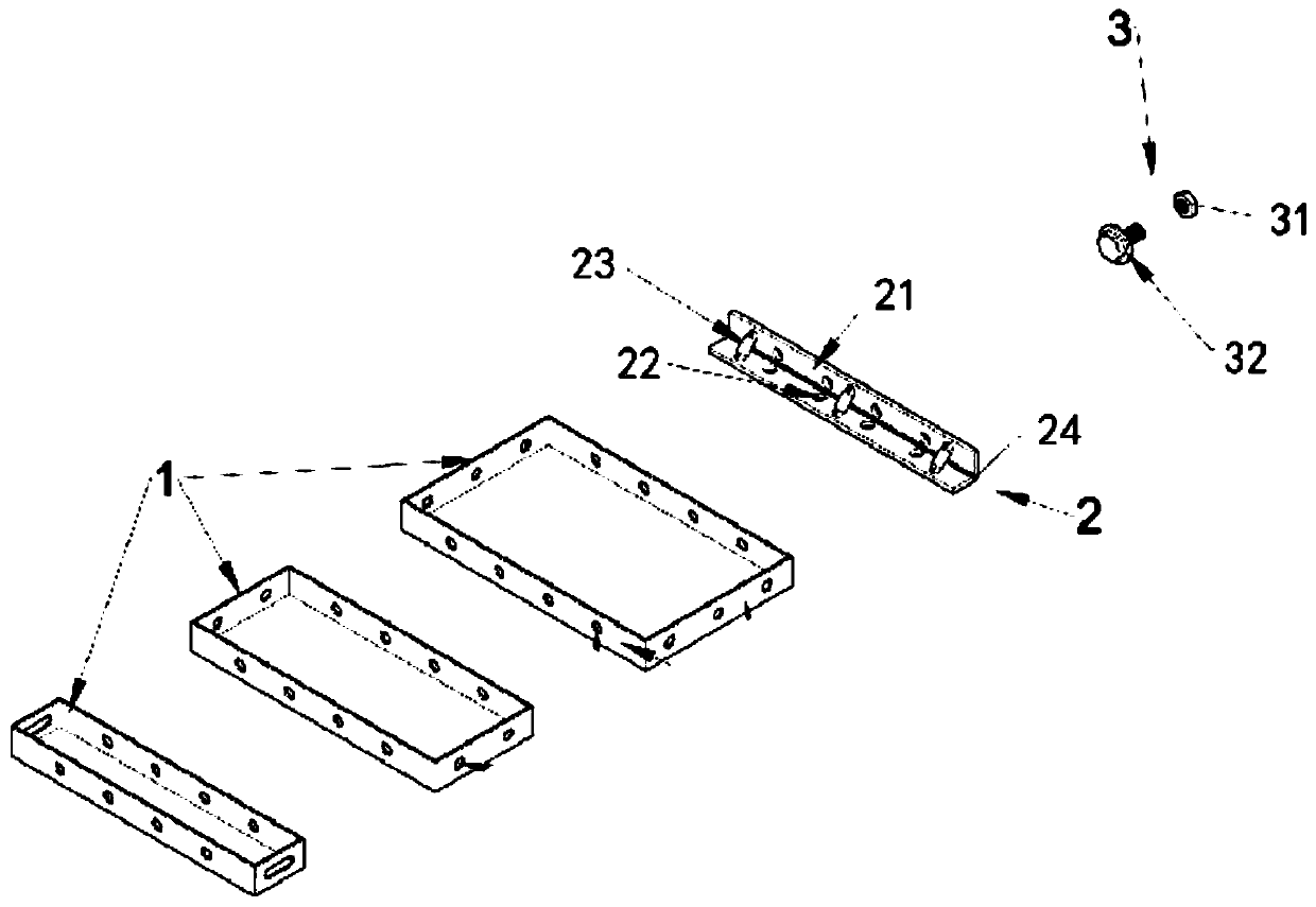
[0028] See figure 1 , figure 2 , image 3 and Figure 4 As shown, the column corner template suitable for prefabricated buildings of the present invention includes a corner connecting plate 21 and a connecting plate 1 detachably connected to both sides of the corner connecting plate 21. The corner connecting plate 21 includes a first hinged joint. The board body 21 and the second board body 22 are connected between the first board body 21 and the second board body 22 with a telescopic piece 23 that controls the angle of the first board body 21 and the second board body 22. The connecting plates 1 on both sides of 21 can be spliced ​​according to the node structure of the project building. Through the selection of the size of the connecting plate 1 and the adjustment of the angle of the corner connecting plate 21, it can be well adapted to the node structure of...


PUM


Abstract

The invention discloses a column corner formwork suitable for a fabricated building and a construction method of the column corner formwork. The column corner formwork is efficient, fast, low in cost, high in recycling rate and wide in application range. The column corner formwork comprises corner connecting plates and connecting plates detachably connected to the two sides of the corner connecting plates, the corner connecting plates comprise first plate bodies and second plate bodies which are mutually hinged, and telescopic parts for controlling the angles of the first plate bodies and the second plate bodies are connected between the first plate bodies and the second plate bodies. The connecting plates on the two sides of the corner connecting plates can be spliced according to the joint structure of the project building, the sizes of the connecting plates are selected, the angles of the corner connecting plates are adjusted, thus the column corner formwork can well adapt to the joint structure of the project building, demounting and mounting are convenient, adaptability is high, the column corner formwork can adapt to various different shapes and can be overall spliced and then hoisted together, the angles of the corner connecting plates can be fine adjusted during mounting after hoisting, the column corner formwork can be fixed firmly, concrete is prevented from leaking, and the pouring quality is ensured.

Description

Technical field [0001] The invention relates to the field of prefabricated buildings, and more specifically to a column corner template suitable for prefabricated buildings and a construction method. Background technique [0002] In the process of prefabricated building construction, the wall panels, beams, columns and other components are prefabricated and cured in the factory in advance, and then transported to the construction site for hoisting and assembly. However, the connection nodes between the wall-pillar-board are mostly used in the assembly process The connection is made by pouring in place. For example, there are a large number of cast-in-place nodes between the column-beam-slab in the assembled monolithic frame structure, and it is difficult to wrap the cast-in-place nodes. [0003] Traditional node wrappers usually use wooden molds for fixed splicing, and then pour concrete. Due to the low strength of wooden molds, easy bending and deformation, and easy expansion and...

Claims


Application Information

Patent Timeline
Patent Type & Authority Applications(China)
IPC IPC(8): E04G13/02
CPCE04G13/028
Inventor 蒋义周林根吕飞何喜陈静刘铁
Owner NINGBO PRECA CONSTR TECH CO LTD
Learn More