Engine cooling system for vehicle and vehicle

An engine cooling and vehicle technology, applied in engine cooling, engine components, machines/engines, etc., can solve the problems of slow engine heating, high fuel consumption, insufficient combustion chamber cooling, etc. Effect

Active Publication Date: 2019-09-17
ZHEJIANG GEELY HOLDING (GROUP) CO LTD +1
View PDF6 Cites 3 Cited by
  • Summary
  • Abstract
  • Description
  • Claims
  • Application Information

AI Technical Summary

Problems solved by technology

[0002] In the current engine cooling system of vehicles, the water pumped by the water pump is directly diverted into the water jacket of the cylinder head, and the water jacket of the cylinder head flows from the inlet to the outlet, and most of them adopt the form of longitudinal flow, which results in insufficient cooling of the combustion chamber. At the same time Engine performance cannot be improved
[0003] At the same time, in the current engine cooling system, the oil cooler is arranged in the small cycle of the engine. When the system starts at low temperature, there is a large amount of heat exchange in the oil cooler, which leads to the consequences of slow engine temperature rise and high fuel consumption. At the same time, this arrangement also makes Anomalies occur when vehicles are heated in winter

Method used


Image

  • Engine cooling system for vehicle and vehicle
  • Engine cooling system for vehicle and vehicle

Examples


Embodiment Construction

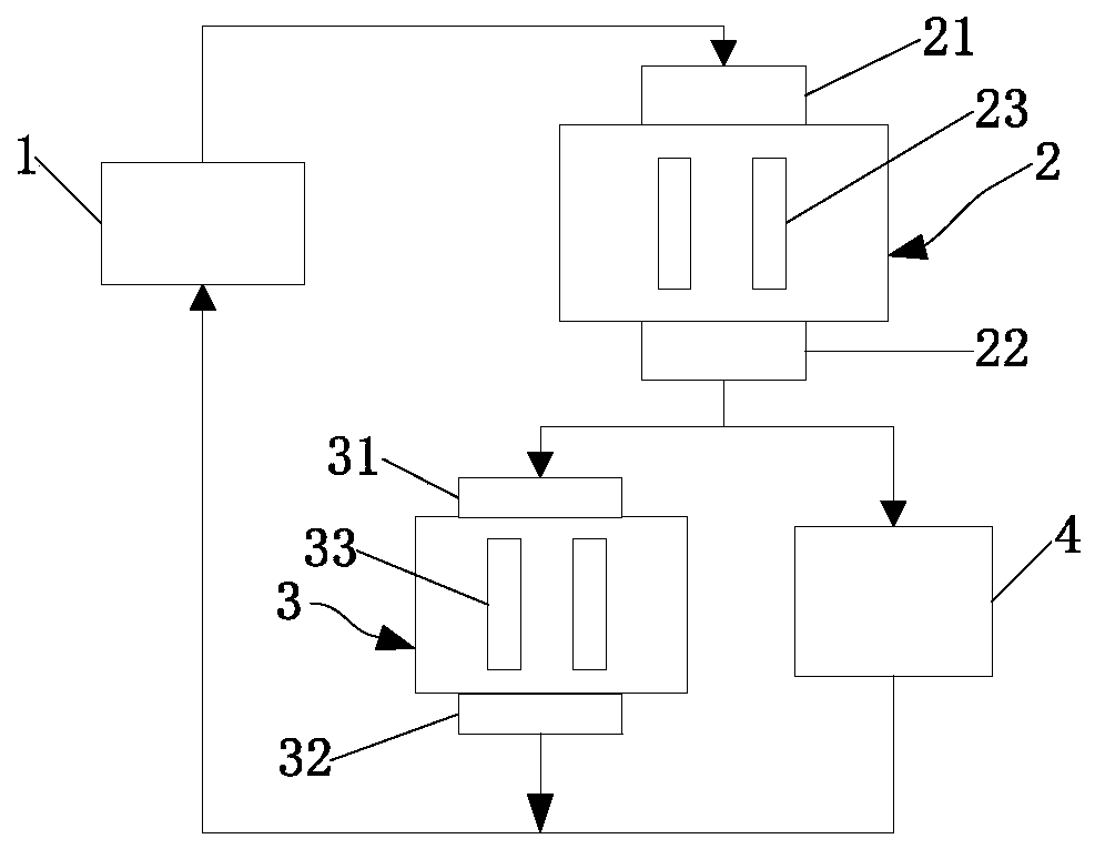
[0035] figure 1 is a functional block diagram of an engine cooling system for a vehicle according to one embodiment of the present invention. like figure 1 As shown, the engine cooling system for a vehicle includes a water pump 1 , a cylinder head combustion chamber water jacket 2 , a cylinder head exhaust water jacket 3 and a cylinder block water jacket 4 . Water pump 1 is used to pump coolant. The cylinder head combustion chamber water jacket 2 communicates with the liquid outlet of the water pump 1 . The cylinder head exhaust water jacket 3 communicates with the liquid outlet of the cylinder head combustion chamber water jacket 2 . The cylinder block water jacket 4 communicates with the liquid outlet of the cylinder head combustion chamber water jacket 2, and the cylinder head exhaust water jacket 3 is connected to the water pump 1 and the cylinder block water jacket 4 in parallel. Between the cylinder head combustion chamber water jacket 2. Wherein, the cylinder head ...


PUM


Abstract

The invention provides an engine cooling system for a vehicle and the vehicle, and relates to the field of the vehicles. The engine cooling system for the vehicle comprises a water pump, a cylinder cover combustion chamber water jacket, a cylinder cover exhaust water jacket and a cylinder body water jacket; the cylinder cover exhaust water jacket and the cylinder body water jacket are connected in parallel between the water pump and the cylinder cover combustion chamber water jacket; the cylinder cover combustion chamber water jacket is provided with a cylinder cover combustion chamber water jacket exhaust side and a cylinder cover combustion chamber water jacket intake side; the cylinder cover combustion chamber water jacket is provided with at least two independent cylinder cover combustion chamber water channels communicating the cylinder cover combustion chamber water jacket exhaust side and the cylinder cover combustion chamber water jacket intake side; the cylinder cover exhaust water jacket is provided with a cylinder cover exhaust water jacket exhaust side and a cylinder cover exhaust water jacket intake side; and the cylinder cover exhaust water jacket is provided with at least two independent cylinder cover exhaust water channels communicating the cylinder cover exhaust water jacket exhaust side and the cylinder cover exhaust water jacket intake side. The invention also provides the vehicle comprising the engine cooling system. The performance of an engine can be greatly improved.

Description

technical field [0001] The invention relates to the field of vehicle technology, in particular to an engine cooling system for a vehicle and the vehicle. Background technique [0002] In the current engine cooling system of vehicles, the water pumped by the water pump is directly diverted into the water jacket of the cylinder head, and the water jacket of the cylinder head flows from the inlet to the outlet, and most of them adopt the form of longitudinal flow, which results in insufficient cooling of the combustion chamber. At the same time Engine performance can't be improved either. [0003] At the same time, in the current engine cooling system, the oil cooler is arranged in the small cycle of the engine. When the system starts at low temperature, there is a large amount of heat exchange in the oil cooler, which leads to the consequences of slow engine temperature rise and high fuel consumption. At the same time, this arrangement also makes Anomalies can occur when vehi...

Claims


Application Information

Patent Timeline
Patent Type & Authority Applications(China)
IPC IPC(8): F01P3/02F02F1/40F02F1/14F01P3/20F01P7/16
CPCF01P3/02F01P3/20F01P7/165F01P2003/024F01P2003/028F02F1/14F02F1/40
Inventor 高金恒殷怀彪何利孙晓阳姚青羚王超
Owner ZHEJIANG GEELY HOLDING (GROUP) CO LTD
Why Eureka
Try Eureka