
Air supply device

An air supply device and fan technology, which is applied to pump devices, components of pumping devices for elastic fluids, non-variable volume pumps, etc., can solve the problems of low air output, not easy to carry, noise, etc. The effect of uniformity, increasing air volume and reducing noise

Active Publication Date: 2019-09-17
DELTA ELECTRONICS INC
View PDF10 Cites 1 Cited by
  • Summary
  • Abstract
  • Description
  • Claims
  • Application Information

AI Technical Summary

Problems solved by technology

In the existing design, since the motor is arranged on a single side of the air supply device, the weight distribution of the air supply device is uneven, making it difficult to carry
In addition, since the motor and fan are close to the air inlet on one side, the air intake volume of the two air inlets is inconsistent
Therefore, when the existing surface drying device is in operation, it is easy to cause noise and the air output is low

Method used


Image

  • Air supply device
  • Air supply device
  • Air supply device

Examples


Embodiment Construction

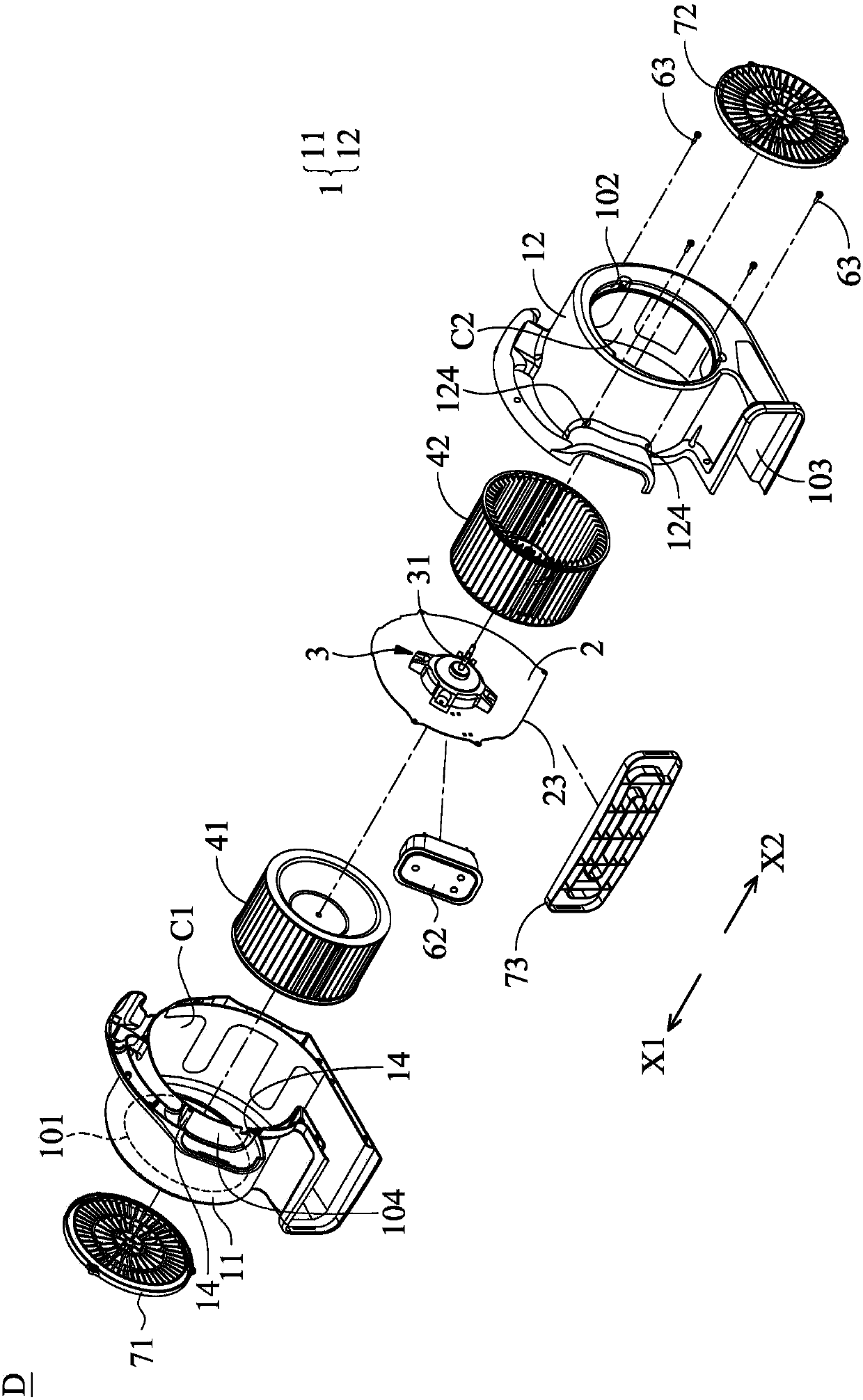
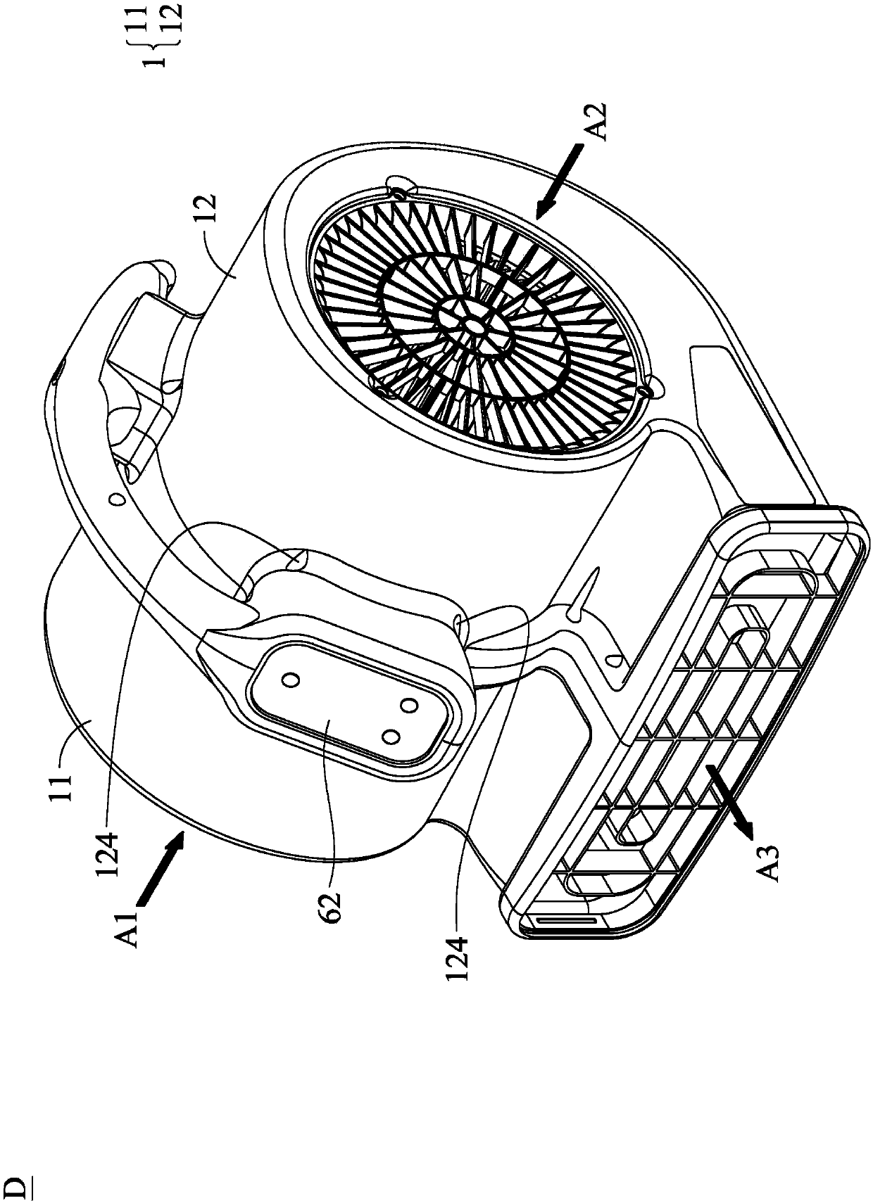
[0074] Figure 1A is an exploded perspective view showing an air blower according to an embodiment of the present invention. Figure 1B It is an assembled view showing an air blower according to an embodiment of the present invention. Referring to FIGS. 1A and 1B , an air blower D according to an embodiment of the present invention includes a housing 1 , a partition 2 , a coaxial motor 3 , a first fan 41 and a second fan 42 . The housing 1 has a first air inlet 101, a second air inlet 102 and an air outlet channel 103, the housing 1 includes a first housing part 11 and a second housing part 12, the first air inlet 101 forms In the first casing part 11 , the second air inlet 102 is formed in the second casing part 12 . The partition 2 is disposed between the first housing part 11 and the second housing part 12 . In an embodiment of the present invention, the first fan and the second fan have the same radius or the same chord length; the size of the first air inlet is the same...


PUM


Abstract

The invention discloses an air supply device. The air supply device comprises a shell, a separation piece, a coaxial motor, a first fan and a second fan. The shell is provided with a first air inlet, a second air inlet and an air outlet channel; the shell comprises a first shell part and a second shell part; the first air inlet is formed in the first shell part; and the second air inlet is formed in the second shell part. The separation piece is arranged between the first shell part and the second shell part. The coaxial motor comprises a rotating shaft, and is arranged on the separation piece; the rotating shaft comprises a first free end and a second free end; the first free end extends in the first direction; and the second free end extends in the second direction. The first fan is connected with the first free end; and the second fan is connected with the second free end.

Description

technical field [0001] The invention relates to an air supply device, in particular to an air supply device with double air inlets. Background technique [0002] A conventional air supply device (for example, a carpet air dryer) has a motor, a fan, two air inlets and an air outlet. In the existing design, since the motor is arranged on a single side of the air supply device, the weight distribution of the air supply device is uneven, making it difficult to carry. In addition, since the motor and the fan are close to the air inlet on one side, the air intake volume of the two air inlets is inconsistent. Therefore, when the existing surface air-drying device is in operation, it is easy to cause noise and the air output is relatively low. Contents of the invention [0003] In order to solve the problems in the prior art, the present invention provides an air supply device, which includes a casing, a partition, a coaxial motor, a first fan and a second fan. The housing has ...

Claims


Application Information

Patent Timeline
Patent Type & Authority Applications(China)
IPC IPC(8): F04D25/16F04D29/42F04D29/66
CPCF04D25/163F04D25/166F04D29/424F04D29/661F04D25/0606F04D17/162F04D25/0693F04D29/4226F04D29/626F04D17/16
Inventor 陈恩枫艾序繁林文祥
Owner DELTA ELECTRONICS INC
Learn More