A device for detecting misalignment of complex profiles in a narrow space and a method for detecting misalignment

A technology with complex profile and narrow space, applied in the field of detection of misalignment, can solve the problems of unreusable sample paste, limited light incident angle, high cost of laser scanning, etc., and achieves a simple structure, low manufacturing cost and convenient operation. Effect

Active Publication Date: 2021-05-04
AECC AVIATION POWER CO LTD
View PDF10 Cites 0 Cited by
  • Summary
  • Abstract
  • Description
  • Claims
  • Application Information

AI Technical Summary

Problems solved by technology

Several methods have their own advantages and disadvantages. The cost of laser scanning is high, and the angle of incidence of light is limited; the method of visual inspection or feeler gauge comparison has large errors, and the measurement cannot be performed if the space is too small or the eyes are blocked; the method of slice projection of proofing paste must have Projector, and the sample paste cannot be reused

Method used


Image

  • A device for detecting misalignment of complex profiles in a narrow space and a method for detecting misalignment
  • A device for detecting misalignment of complex profiles in a narrow space and a method for detecting misalignment
  • A device for detecting misalignment of complex profiles in a narrow space and a method for detecting misalignment

Examples


Embodiment 1

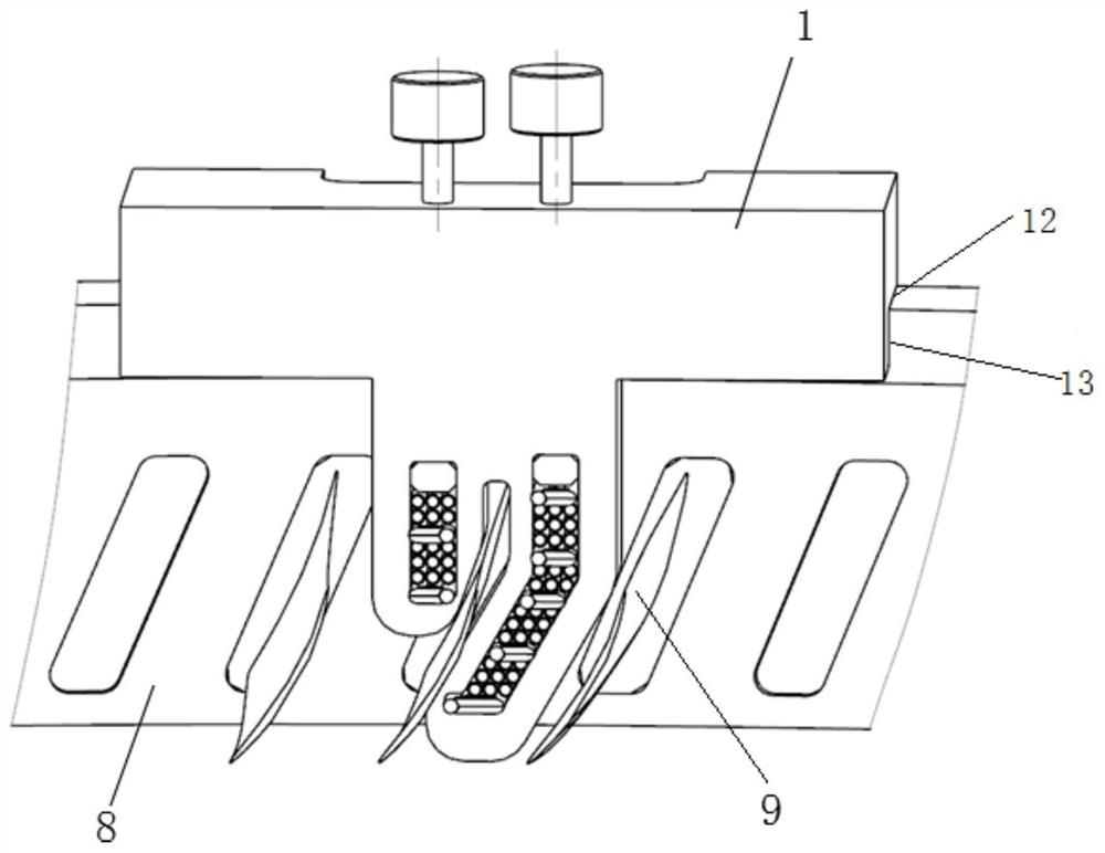
[0049] Such as image 3 As shown, the second part 9 needs to be installed in the hole on the first part 8, and it is required to detect the displacement of the mounting surface of the second part 9 on the part one 8 relative to the arc surface of the first part 8. According to the characteristics of part 18, an end face 12 and an arc surface 13 are designed on the body 1 as the positioning surface. Because the displacement of the parts in the same axial section is the same, there is no need to limit the position along the arc surface when the detection device is used. turn.

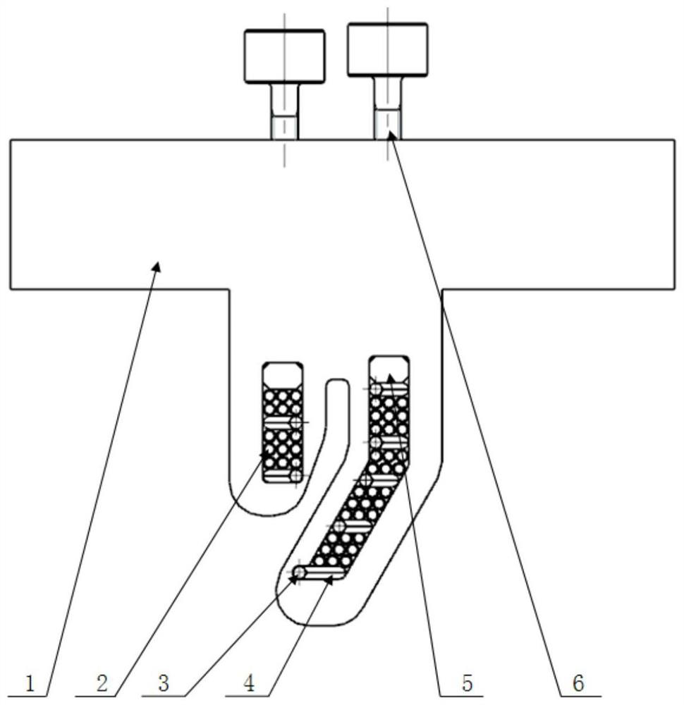
[0050]For the installation structure of part 1 and part 2, the lower half has a first measuring end and a second measuring end, and there is a gap between the first measuring end and the second measuring end. Due to the narrow measurement space, an irregularly shaped body 1 is designed according to the measurement space, and through holes are opened on the first measuring end and the second measuring end...

Embodiment 2

[0053] refer to image 3 To illustrate, there is no part 2 9, and what is required to be detected is the concave and convex amount of the arc surface of part 1 8 itself. At this time, the measured profile and the misaligned profile are the profile of a component. The measuring terminal can be designed as one or more.

[0054] When measuring, the body 1 and the part 18 are positioned well, and the lead-out pin 3 and the L-shaped measuring pin 4 are pressed down by hand, and the lead-out pin 3 and the L-shaped measuring pin 4 are in contact with the profile of the part 18, and the clamping screw 6 is tightened , then take out the detection device, observe the rear end surface of the lead-out needle 3 and the L-shaped measuring needle 4, or judge with the help of a tool, if the end surface of the lead-out needle 3 is between the step surface 11 of the L-shaped measuring needle 4 or is aligned with any end surface of the step surface 11 If it is flat, the amount of misalignment i...


PUM


Abstract

The invention discloses a device for detecting the misalignment of complex profiles in a narrow space, which comprises a body, and a through hole is opened on the body, and several groups of measuring needles and several spacer needles are arranged in the through hole. Spacer needles are arranged between them; each group of measuring needles includes a lead-out needle and an L-shaped measuring needle, the front end of one needle is in contact with the measured surface, and the front end of the other needle is in contact with the misplaced surface; The back end of the lead-out needle is a plane, and the back end of the L-shaped measuring needle is a stepped surface, and the distance between the stepped surfaces is the preset misalignment; when measuring, press the lead-out needle and the L-shaped measuring needle by hand to move the complex shape. The misalignment between the surfaces is converted to the rear end surface of the lead-out needle and the L-shaped measuring needle. By observing the position of the step surface of the lead-out needle and the L-shaped measuring needle, it is judged whether the measured misalignment is qualified. The principle of judgment is simple, the process is simple, the technical requirements for workers are low, the operation is convenient for workers, and the work efficiency is high.

Description

technical field [0001] The invention belongs to the technical field of misalignment detection devices, and in particular relates to a misalignment detection device for complex profiles in a narrow space and a method for detecting misalignment. Background technique [0002] At present, for the detection of misalignment between complex profiles in a narrow space, laser scanning can be used for higher precision, visual inspection or feeler gauge comparison can be used for low precision, and proofing paste and slice projection can also be used. method. Several methods have their own advantages and disadvantages. The cost of laser scanning is high, and the angle of incidence of light is limited; the method of visual inspection or feeler gauge comparison has large errors, and the measurement cannot be performed if the space is too small or the eyes are blocked; the method of slice projection of proofing paste must have Projector, and the sample paste cannot be reused. Contents ...

Claims


Application Information

Patent Timeline
Patent Type & Authority Patents(China)
IPC IPC(8): G01B5/00
CPCG01B5/00
Inventor 王荣郭霞孔令姗李莎王素娟苏琳牛阿妮罗雄狮
Owner AECC AVIATION POWER CO LTD
Why Eureka
Try Eureka