
Asymmetrical transmitter

A transmitter, asymmetric technology, applied in the direction of instruments, optics, diffraction grating, etc., can solve the problem of large volume

Active Publication Date: 2019-09-17
HUAZHONG UNIV OF SCI & TECH
View PDF6 Cites 1 Cited by
  • Summary
  • Abstract
  • Description
  • Claims
  • Application Information

AI Technical Summary

Problems solved by technology

[0004] The present invention solves the defect of large volume existing in current asymmetrical transmitters by providing an asymmetrical transmitter

Method used


Image

  • Asymmetrical transmitter
  • Asymmetrical transmitter
  • Asymmetrical transmitter

Examples


Embodiment Construction

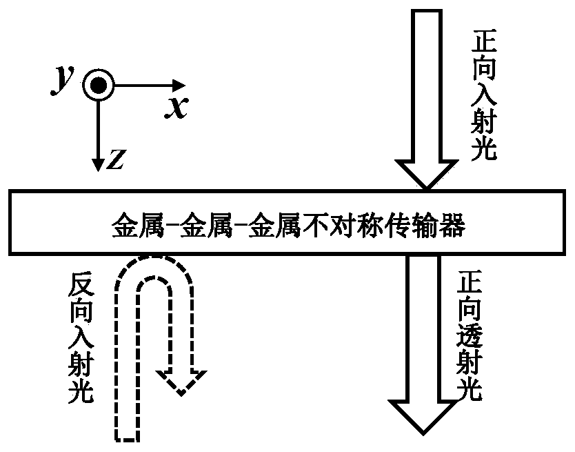
[0025] The embodiment of the present invention provides an asymmetric transmitter, which can realize the effect of forward propagation and reverse isolation in a narrow wavelength range, and solves the defect of large volume existing in the current asymmetric transmitter.

[0026] The technical solution in the embodiment of the present invention is to solve the above-mentioned problems, and the general idea is as follows:

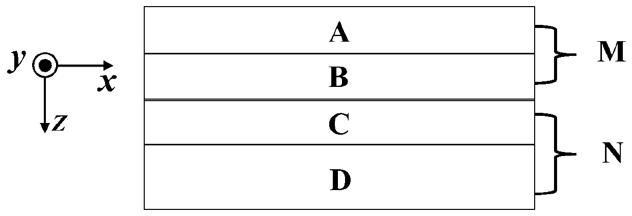
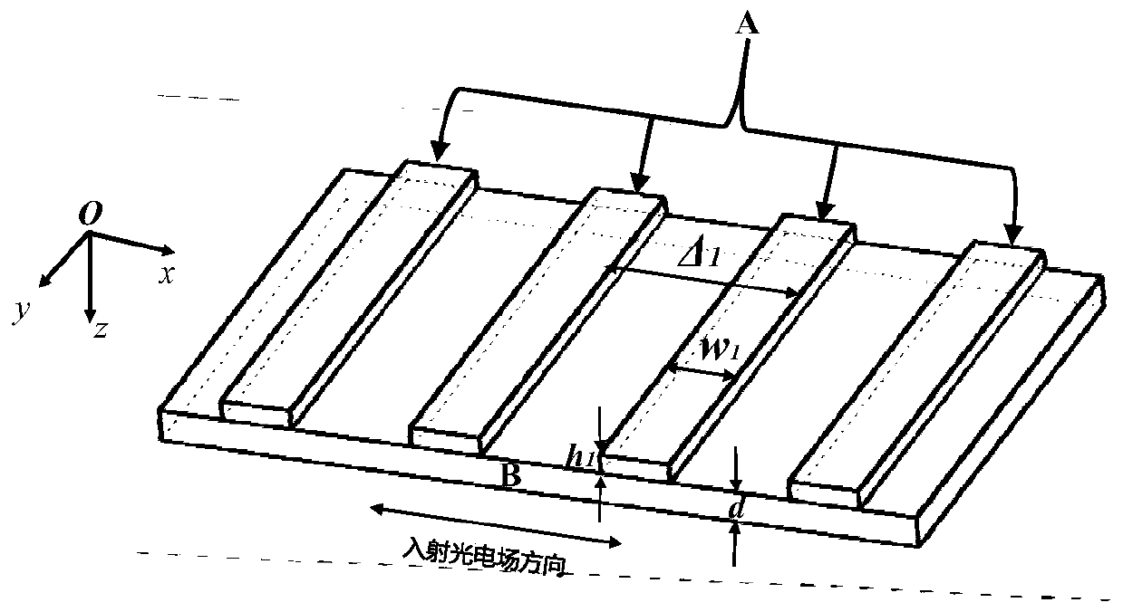
[0027] The embodiment of the present invention utilizes an asymmetric grating with a metal-metal-metal structure to unidirectionally excite surface plasmon polaritons (SPPs), thereby realizing asymmetric transmission. SPPs are a kind of electromagnetic wave mode propagating along the medium / metal interface, which is a special kind of surface wave. Its field strength decays exponentially along the direction perpendicular to the interface. According to the dispersion relation of SPPs, at the same frequency, the wave vector k of light in vacuum 0 Wave vector...


PUM

PropertyMeasurementUnit
thicknessaaaaaaaaaa
thicknessaaaaaaaaaa
grating periodaaaaaaaaaa

Abstract

The invention discloses an asymmetrical transmitter. The asymmetrical transmitter comprises a first metal grating layer, a metal layer, a second metal grating layer and a dielectric substrate which are sequentially arranged in a stacked manner, wherein structure parameter values of the first metal grating layer satisfy preset parameter conditions, so that light waves emitted on the surface of the first metal grating layer are converted into surface plasmon polaritons (SPPs); the metal layer blocks transmission of the light waves emitted sequentially through the dielectric substrate and the second metal grating layer, and the thickness of the metal layer is smaller than a penetration depth of the SPPs in a corresponding metal, so that the SPPs obtained through the conversion on the surface of the first metal grating layer enter the second metal grating layer; the second metal grating layer is embedded in the dielectric substrate, and a grating constant of the second metal grating layer is different from a grating constant of the first metal grating layer; and structure parameter values of the second metal grating layer do not satisfy the preset parameter conditions, so that the light waves emitted on the surface of the second metal grating layer cannot be converted into the SPPs. The asymmetrical transmitter disclosed by the invention has the advantage that the defect of a large size of the conventional asymmetrical transmitter is overcome.

Description

technical field [0001] The invention relates to the technical field of optical devices, in particular to an asymmetric transmitter. Background technique [0002] Asymmetric transmitter is an optical passive device, which plays an indispensable role in optical communication, optical network, and can be used to control or cancel noise, protect the light source in lasers and one-way detection / one-way sensing system etc. Its function is to allow transmission when a beam of light is incident from a certain direction; but when the beam of light is incident in the opposite direction, the transmittance is very low. [0003] The realization of an asymmetric transmitter often needs to break the time-domain symmetry of the system, but the current asymmetric transmitter has the disadvantage of large volume. Contents of the invention [0004] By providing an asymmetrical transmitter, the present invention solves the defect of large volume existing in the current asymmetrical transmit...

Claims


Application Information

Patent Timeline
Patent Type & Authority Applications(China)
IPC IPC(8): G02B5/00G02B5/18
CPCG02B5/008G02B5/18
Inventor 黄黎蓉巴春发令永红
Owner HUAZHONG UNIV OF SCI & TECH
Learn More