
Cam actuated switch module and manufacturing method thereof

A switch module and actuating switch technology, applied in the direction of electric switches, contact drive mechanisms, electrical components, etc., can solve the problems of increasing power, increasing power loss, increasing raw material usage, etc., to reduce size and reduce power loss , the effect of large space optimization

Pending Publication Date: 2019-09-17
GORLAN TEAM S L U
View PDF13 Cites 0 Cited by
  • Summary
  • Abstract
  • Description
  • Claims
  • Application Information

AI Technical Summary

Problems solved by technology

[0010] However, the use of bridges implies some disadvantages, namely: increasing the resistance of the terminals, which in turn increases power loss, increasing the amount of raw material used to manufacture the switch, and increasing the size of the switch
Additionally, the interface area between the bridge and the terminals to which the bridge is screwed are hot spots that significantly increase power (heat) losses

Method used


Image

  • Cam actuated switch module and manufacturing method thereof
  • Cam actuated switch module and manufacturing method thereof
  • Cam actuated switch module and manufacturing method thereof

Examples


Embodiment Construction

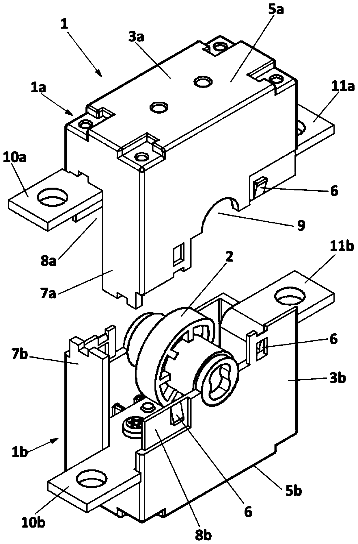
[0039] Such as figure 1 As shown in the example shown, the switch module 1 of the present invention consists of two identical half-modules (1a, 1b) connected to each other and by the two half-modules (1a, 1b) held when they are assembled Rotary cam (2) constitutes.

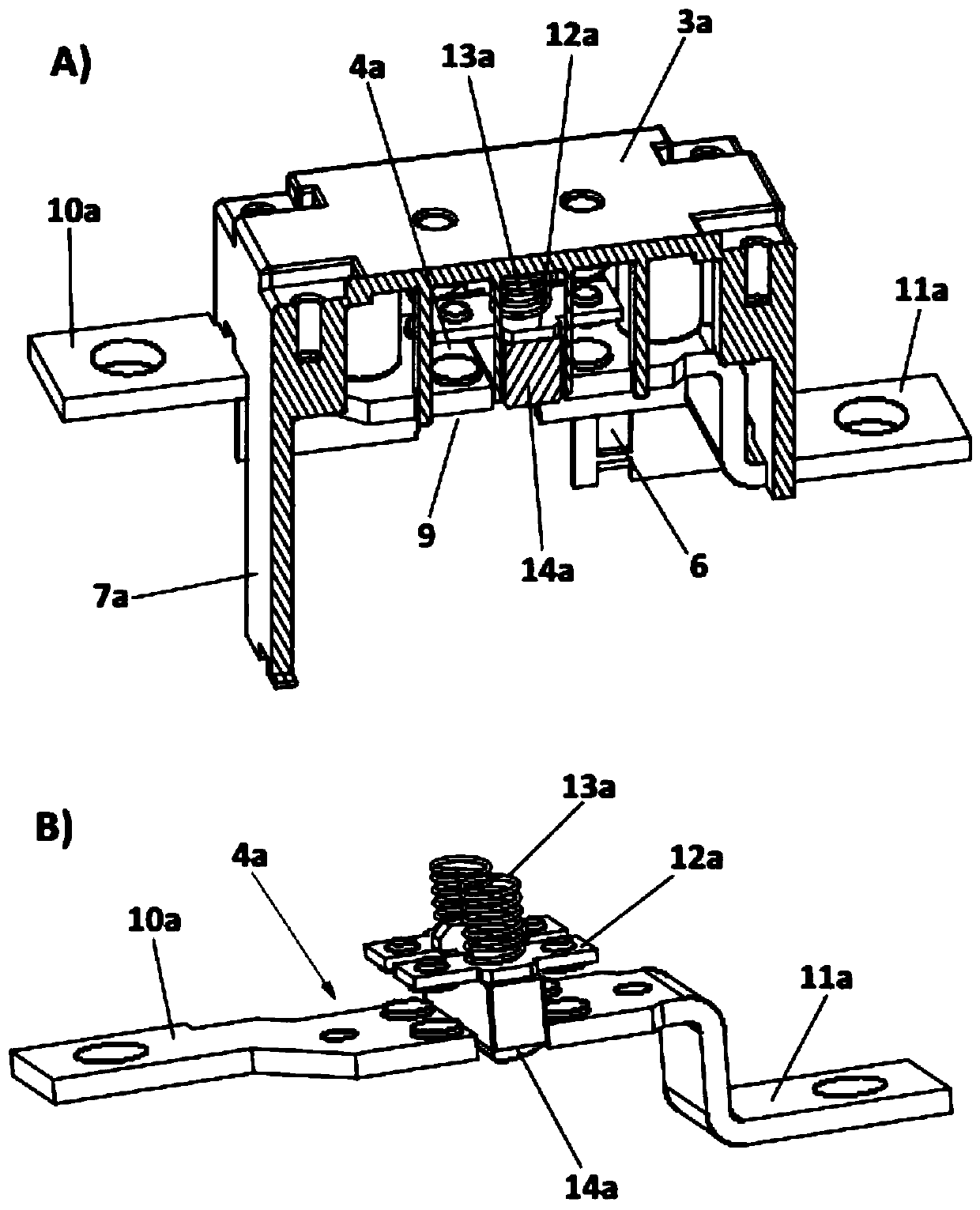
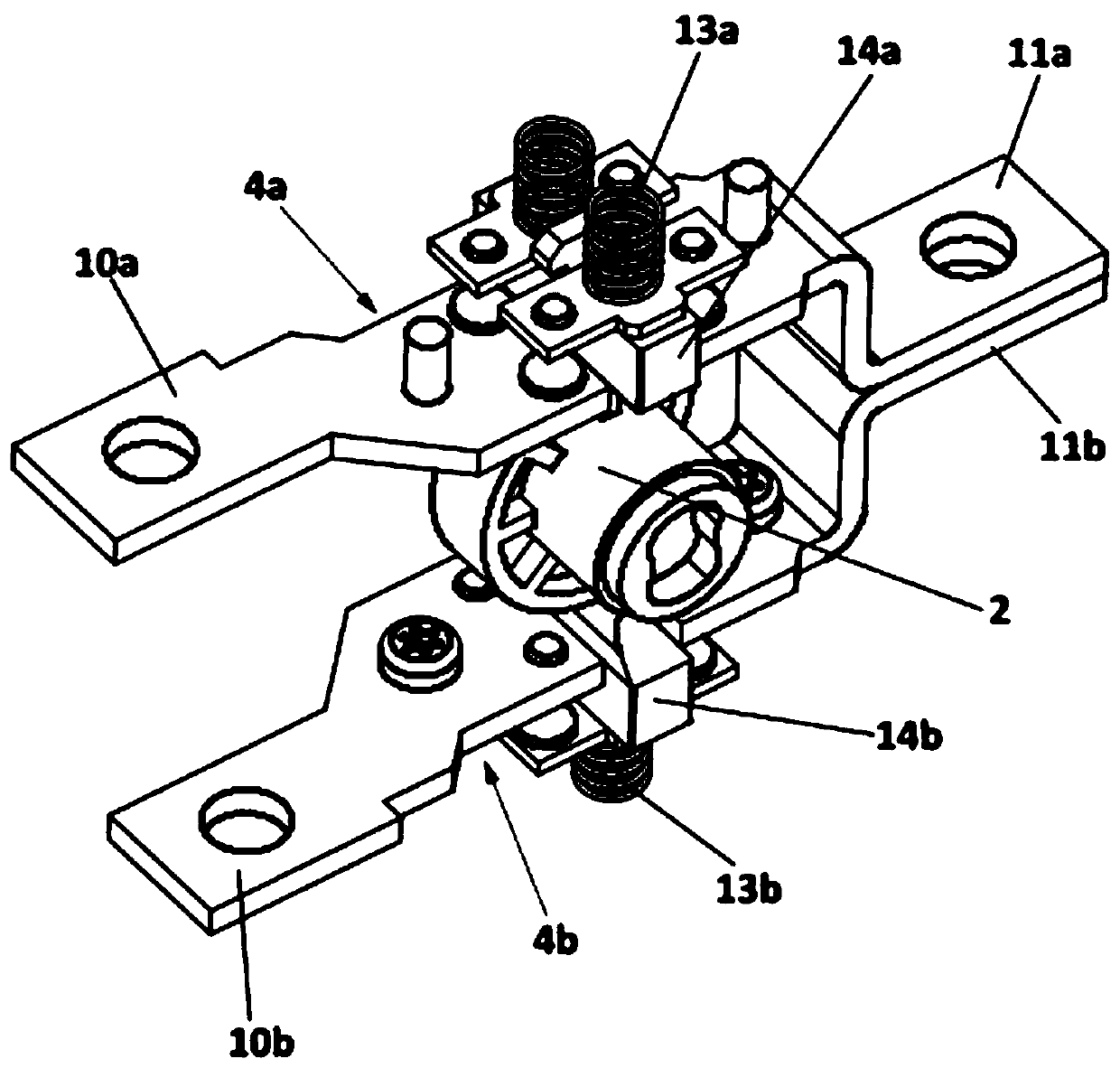
[0040] Both the first module (1a) and the second half-module (1b) comprise two identical half-shells (3a, 3b), and two identical switches (4a, 4b), the switches (4a, 4b) are respectively mounted on The interior of the half shells (3a, 3b). The half-shells (3a, 3b) are made of moldable and electrically insulating material, since they are molded in the same mould, they are identical in structure.

[0041] The first half-shell (3a) and the second half-shell (3b) have two semicircular cutouts (9) which define a circular opening (15), for example when the two half-shells are assembled, The cylindrical part of the cam (2) can be accommodated in the opening (15) and can be rotated and guided in the opening (15).

[0...


PUM


Abstract

The present invention refers to a cam actuated switch module and to its manufacturing method. The module is made up of two identical semi-modules attachable to each other, the semi-modules comprising two identical casing halves and two identical switches, respectively fitted inside the first and second casing halves. A rotatable cam is placed inside the casing and configured for selectively open and close the first and second switches upon rotation of the cam. The first and second casing halves have at least one recess, such as when they are attached to each other, the recesses define an opening, and a part of the cam is received in the opening and it is rotatable therein. One of the first fixed contact is conformed such as when the first and second casing halves are assembled to each other, its part protruding outside the casing, is in contact with the corresponding fixed contact, thus, the use of external bridges is eliminated.

Description

technical field [0001] The present invention generally relates to the construction of cam-actuated switches and diverter switches. [0002] It is an object of the present invention to provide a low cost cam operated switch which reduces production time by reducing manufacturing costs and simplifying manual assembly of the switch. [0003] Another object of the present invention is to provide a more efficient transfer switch (commutator) to reduce power loss during quiescent conditions, ie when current flows through the switch. [0004] Yet another object of the present invention is to provide a switch with reduced size and increased durability, ie capable of performing a large number of switching operations. Background technique [0005] As is well known, a cam switch generally includes two or more pairs of fixed contacts connected to corresponding circuits, and movable contacts arranged to act on the fixed contacts based on the rotation of the cam to selectively close and ...

Claims


Application Information

Patent Timeline
IPC IPC(8): H01H3/42H01H9/00H01H11/00
CPCH01H3/42H01H9/0027H01H11/0006H01H19/626H01H19/64H01H2011/0093
Inventor 何塞·奥斯卡·安达卢兹·索利
Owner GORLAN TEAM S L U
Learn More