
An electrical control cabinet for maintenance vehicles

A technology for electrical control cabinets and vehicles, applied in the field of control cabinets, can solve problems such as poor use effect and potential safety hazards, and achieve the effects of simple structure, accelerated heat dissipation, and convenient use

Inactive Publication Date: 2020-12-22
CHANGSHA UNIVERSITY
View PDF4 Cites 0 Cited by
  • Summary
  • Abstract
  • Description
  • Claims
  • Application Information

AI Technical Summary

Problems solved by technology

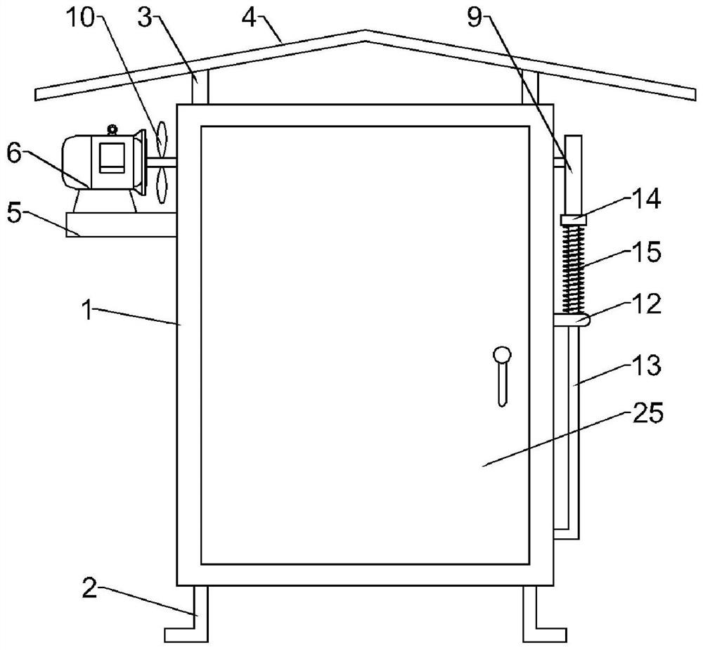
[0003] Electrical cabinets are required in the vehicle maintenance industry, and are frequently used outdoors. In the hot summer, if the heat in the electrical cabinets cannot be discharged in time, it will cause a greater safety hazard
Chinese patent (notification number: CN109462153A) discloses an energy-saving and heat-dissipating electrical cabinet. Although the device can dissipate heat and collect energy through solar panels, the actual use of the device is not good after being used in the vehicle maintenance industry

Method used


Image

  • An electrical control cabinet for maintenance vehicles
  • An electrical control cabinet for maintenance vehicles
  • An electrical control cabinet for maintenance vehicles

Examples


Embodiment 1

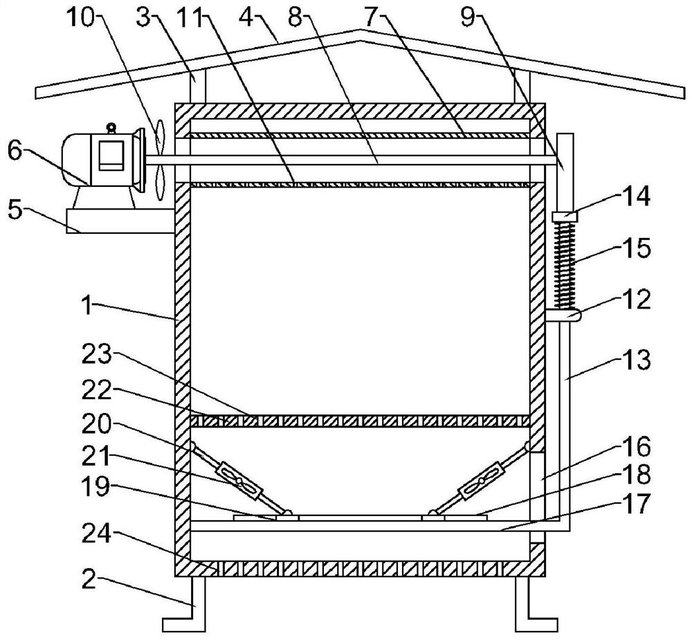
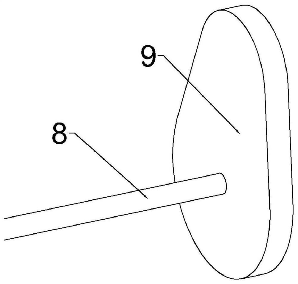
[0021] Example 1: Please refer to Figure 1-4 , an electrical control cabinet for maintenance vehicles, comprising a cabinet body 1, a fixed frame 5 fixedly connected to the upper left of the cabinet body 1, a motor 6 fixedly connected above the fixed frame 5, a horizontal pipe 7 fixedly connected to the top of the cabinet body 1, and a horizontal pipe 7 The left and right sides run through the cabinet body 1, the output end of the motor 6 is fixedly connected with a horizontal shaft 8, the horizontal shaft 8 runs through the horizontal pipe 7 and is connected with a cam 9, the cam 9 is located on the right side of the cabinet body 1, and the left end of the horizontal shaft 8 is fixed A spiral fan blade 10 is connected, and a number of cooling air holes 11 are provided at the bottom of the horizontal tube 7;

[0022] Turn on the motor 6 during use, the rotation of the motor 6 drives the horizontal shaft 8 to rotate, the rotation of the horizontal shaft 8 can drive the rotatio...

Embodiment 2

[0032] Embodiment 2: This embodiment is a further improvement of the previous embodiment: the heat dissipation fan 21 placed horizontally is fixed in the middle of the limit chute 18, and the heat dissipation is always upward during the up and down movement of the limit chute 18, effectively improving the heat dissipation efficiency .

[0033] The working principle of the present invention is: turn on the motor 6 when in use, the rotation of the motor 6 drives the horizontal shaft 8 to rotate, the rotation of the horizontal shaft 8 can drive the rotation of the cam 9, and at the same time drive the rotation of the spiral fan blade 10, and the rotation of the spiral fan blade 10 can drive the air flow After the horizontal pipe 7 moves to the right, based on the principle of jet flow, the flowing air will bring the airflow outside the cooling air hole 11 into the horizontal pipe 7 and blow it out to the right for heat dissipation. During the rotation of the cam 9, the longitudina...


PUM


Abstract

The invention discloses an electrical control cabinet for maintenance vehicles, and relates to a control cabinet, which includes a cabinet body, a fixed frame fixedly connected to the upper left of the cabinet body, a motor fixedly connected above the fixed frame, and a horizontal pipe fixedly connected to the top of the cabinet body. The left and right sides of the horizontal pipe run through the cabinet, the output end of the motor is fixedly connected with a horizontal shaft, the horizontal shaft runs through the horizontal pipe and is connected with a cam, the cam is located on the right side of the cabinet, the left end of the horizontal shaft is fixedly connected with a spiral fan blade, the horizontal pipe The bottom is provided with a number of cooling air holes; the right side of the cabinet body is fixedly connected with a guide bracket, and the inner side of the guide bracket is slidingly connected with a longitudinal transmission rod. The invention is simple in structure and easy to use. When in use, it is driven by a motor to realize the up and down movement of the limit chute, and then drives the heat dissipation fan to continuously change the wind direction to realize heat dissipation to different positions in the cabinet without dead heat dissipation. In addition, the device can be directly and quickly moved The airflow at the top of the cabinet is brought out to accelerate the cooling effect.

Description

technical field [0001] The invention relates to a control cabinet, in particular to an electric control cabinet for maintenance vehicles. Background technique [0002] The electrical cabinet is a cabinet made of steel to protect the normal operation of components. The materials for making electrical cabinets are generally divided into two types: hot-rolled steel plates and cold-rolled steel plates. Compared with hot-rolled steel sheets, cold-rolled steel sheets are softer and more suitable for the production of electrical cabinets. Electrical cabinets are widely used mainly in chemical industry, environmental protection industry, power system, metallurgical system, industry, nuclear power industry, fire safety monitoring, transportation industry and so on. [0003] Electrical cabinets are required in the vehicle maintenance industry, and are frequently used outdoors. In the hot summer, if the heat in the electrical cabinets cannot be discharged in time, there will be a gre...

Claims


Application Information

Patent Timeline
Patent Type & Authority Patents(China)
IPC IPC(8): H05K5/02H05K7/20
CPCH05K5/0217H05K5/0234H05K7/20172H05K7/20145H05K5/03
Inventor 冯婉张文娟张志刚饶瑜
Owner CHANGSHA UNIVERSITY
Learn More