Compressor

A technology for a compressor and a compression mechanism, applied in the field of compressors, can solve the problems of low stability, large heat release, and reduced reliability of refrigeration cycle devices.

Inactive Publication Date: 2019-09-17
MITSUBISHI ELECTRIC CORP
View PDF8 Cites 0 Cited by
  • Summary
  • Abstract
  • Description
  • Claims
  • Application Information

AI Technical Summary

Problems solved by technology

However, the stability of HFO-1123 (hereinafter referred to as R1123 refrigerant), which is a kind of hydrofluoroolefin, is lower than that of conventional refrigerants such as R32 refrigerant and R410A refrigerant, and there is a large risk of disproportionation reaction. Concerns about heat release and reduced reliability of compressors and refrigerat...

Method used


Image

  • Compressor
  • Compressor
  • Compressor

Examples


Embodiment approach 1

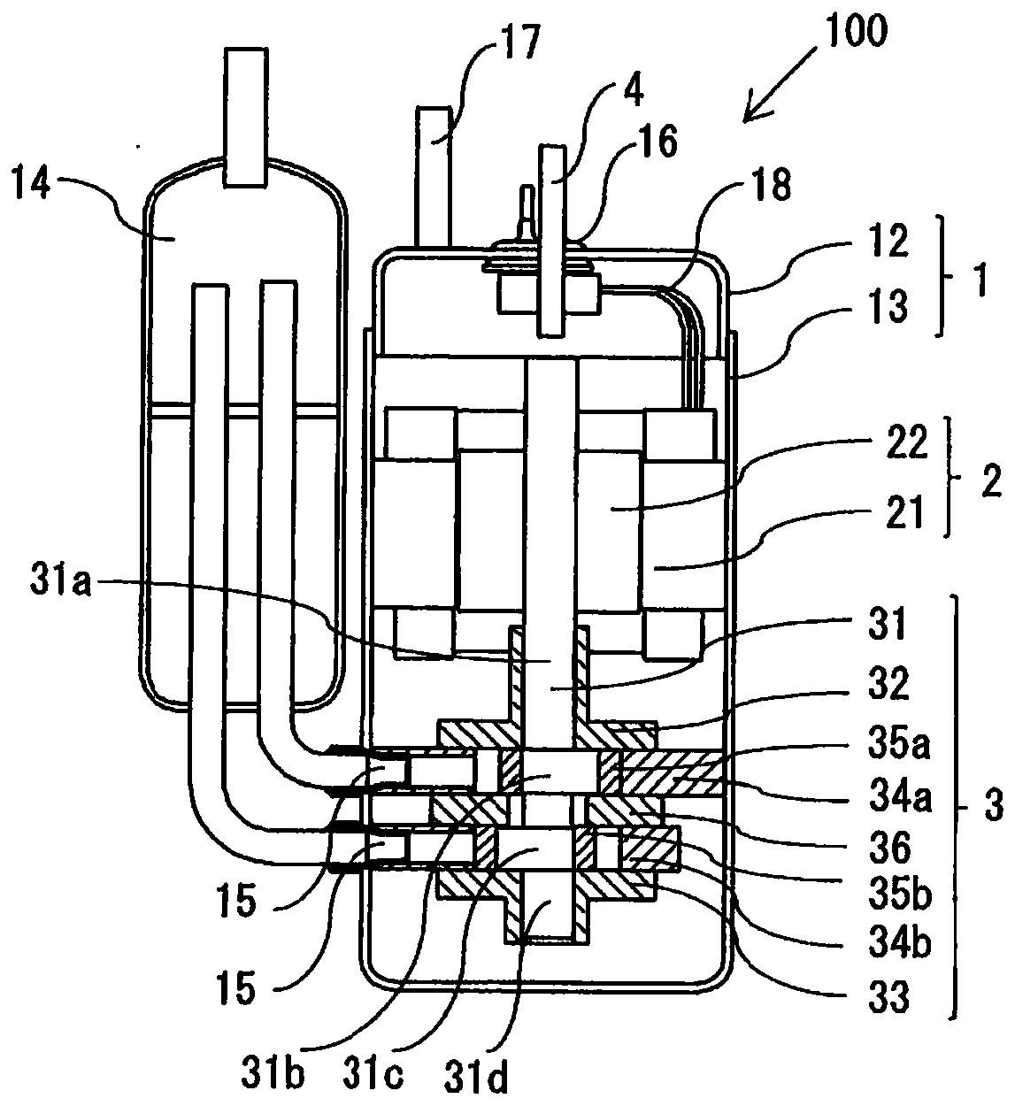
[0020] figure 1 It is an internal configuration diagram showing the inside of the compressor according to Embodiment 1 of the present invention. In the following description, as a compressor, a twin-rotor compressor 100 having two cylindrical cylinders in a compression mechanism will be described as an example. Such as figure 1 As shown, the compressor 100 is a hermetic electric compressor including a sealed container 1 , and a motor unit 2 and a compression mechanism unit 3 inside the sealed container 1 .

[0021] The airtight container 1 is composed of a bottomed cylindrical lower airtight container 13 and an upper airtight container 12 that closes the upper opening of the lower airtight container 13 . The connection part of the lower airtight container 13 of the airtight container 1 and the upper airtight container 12 is fixed by welding, which ensures the airtight state.

[0022] A suction pipe 15 is connected to the lower airtight container 13 , and a suction muffler 1...

Embodiment approach 2

[0086] The compressor according to Embodiment 1 of the present invention has been described in which a single refrigerant of R1123 refrigerant which is one type of hydrofluoroolefin is used as the operating refrigerant of the compressor 100 . In the compressor according to Embodiment 2 of the present invention, other operating refrigerants used in compressor 100 will be described.

[0087] The operating refrigerant is not limited to the single refrigerant of the R1123 refrigerant, and the R1123 refrigerant and the R32 refrigerant may be mixed and used in order to ensure the refrigeration capacity. Among them, the GWP of the mixed refrigerant is preferably less than 500, more preferably less than 100.

[0088] Table 2 shows a pressure comparison and physical property values ​​of a refrigerant mixture between the R1123 refrigerant and the R32 refrigerant used as a conventional refrigerant. The operating conditions of the compressor were obtained by setting the condensing temper...

Embodiment approach 3

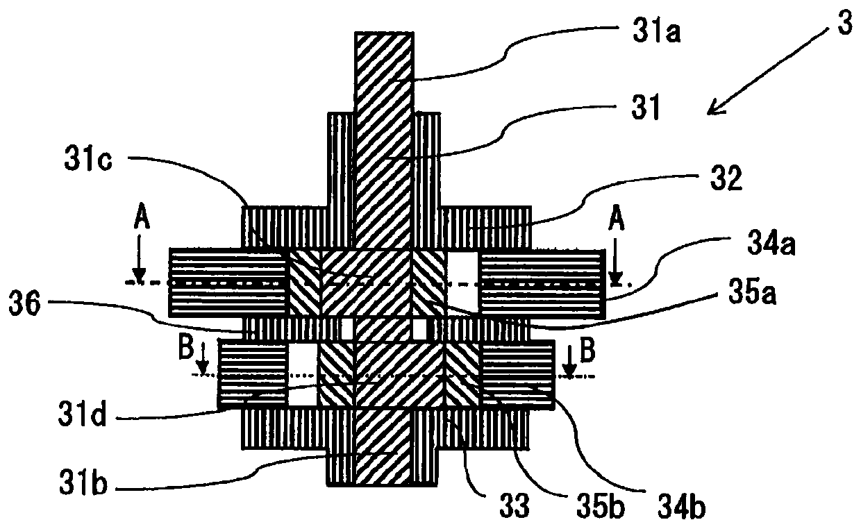
[0127] In the compressor according to Embodiment 3 of the present invention, solid lubrication treatment is performed on the rotary shaft 31 of the compressor 100 . In addition, the main bearing 32 or the sub-bearing 33 may be subjected to solid lubrication treatment together with the rotating shaft 31 or may be subjected to the solid lubrication treatment on the main bearing 32 or the sub-bearing 33 instead of the rotating shaft 31 . By performing solid lubrication treatment on the rotating shaft 31 , the main bearing 32 and the sub-bearing 33 , the heat-generating sticking between the rotating shaft 31 and the main bearing 32 or between the rotating shaft 31 and the sub-bearing 33 during operation of the R1123 refrigerant can be further suppressed.

[0128] In addition, when the tip portion of the sub shaft portion 31b of the rotating shaft 31 is in contact with the inner wall of the sub bearing 33 as a support point, the sub shaft portion 31b may be selectively subjected to ...


PUM


Abstract

This compressor is provided with a sealed container, a compression mechanism which is housed in the sealed container and which compresses a refrigerant flowing into the sealed container. The compression mechanism comprises a rotation shaft, a main bearing and an auxiliary bearing. The coaxiality R [mu m], which is the distance between the central axis E of the main bearing and the central axis F of the auxiliary bearing, satisfies expressions 2 and 6, on the basis of the clearance XA [mu m] representing the difference between the inner diameter DA of the main bearing and the diameter dA of the main shaft part of the rotation shaft located in the main bearing, the clearance XB [mu m] representing the difference between the inner diameter DB of the auxiliary bearing and the diameter dB of the auxiliary shaft part of the rotation shaft located in the auxiliary bearing, the shaft deflectionCA [mu m] representing the shaft deflection of the main shaft part, the shaft deflection CB [mu m] representing the shaft deflection of the auxiliary shaft part, and, when the distance between the lower end of the auxiliary bearing and the upper end of the main bearing is defined as 1 (reference), the ratio alpha of the distance between the lower end and the upper end of the main bearing and the ratio beta of the distance between the lower end and the upper end of the auxiliary bearing.

Description

technical field [0001] The present invention relates to a compressor for compressing and discharging refrigerant. Background technique [0002] Hydrofluoroolefins are refrigerants that have a lower GWP (Global Warming Potential) than R410A refrigerants or R32 refrigerants used as conventional refrigerants, and are expected to be used as refrigerants for countermeasures against global warming . In view of this, a compressor using a hydrofluoroolefin-based operating refrigerant has been proposed (for example, refer to Patent Document 1). [0003] Patent Document 1: Japanese Unexamined Patent Publication No. 2012-57503 [0004] As described above, hydrofluoroolefins or hydrocarbons are refrigerants that have a smaller GWP than conventional refrigerants such as R410 or R32 refrigerants, and are expected to be used as refrigerants for countermeasures against global warming. However, the stability of HFO-1123 (hereinafter referred to as R1123 refrigerant), which is a kind of hy...

Claims


Application Information

Patent Timeline
IPC IPC(8): F04C29/00F04C18/356
CPCF04C18/356F04C29/005F04C2240/50F04C29/00F04C2240/605F04C2210/26F05B2210/14F05B2240/60
Inventor 滨田亮杉浦干一朗木本贵也
Owner MITSUBISHI ELECTRIC CORP
Why Eureka
Try Eureka