A metal additive manufacturing system

A manufacturing system and metal additive technology, applied in the field of metal additive manufacturing, can solve the problems of long working time, waste of working time, and long time required for printing products, shorten the time for filling protective gas, improve printing work efficiency, The effect of reducing the measurement time

Active Publication Date: 2021-10-22
BEIJING WANWEI ADDITIVE MFG TECH CO LTD
View PDF9 Cites 0 Cited by
  • Summary
  • Abstract
  • Description
  • Claims
  • Application Information

AI Technical Summary

Problems solved by technology

[0004] (1) The sealed space of the existing metal additive manufacturing system is large, and the metal additive manufacturing system needs to work in the atmosphere of protective gas, so it is often necessary to fill the sealed space of the metal additive manufacturing system with protective gas. The sealing space is large, and it takes a long time to fill the protective gas. After the workpiece is printed, the door needs to be opened. In this way, it takes a long time to fill the protective gas during processing, which greatly wastes the auxiliary processing time and reduces the processing efficiency. ;
[0005] (2) The existing metal additive manufacturing systems all use a single cladding head. Considering the accuracy of the final printed product, the width of the general cladding head is relatively thin, so the working time of the printed product is relatively long and the work efficiency is low ;
[0006] (3) The organic combination of printing and measurement cannot be realized, that is, online measurement cannot be realized, which wastes working time and reduces production efficiency

Method used


Image

  • A metal additive manufacturing system
  • A metal additive manufacturing system
  • A metal additive manufacturing system

Examples


specific Embodiment approach

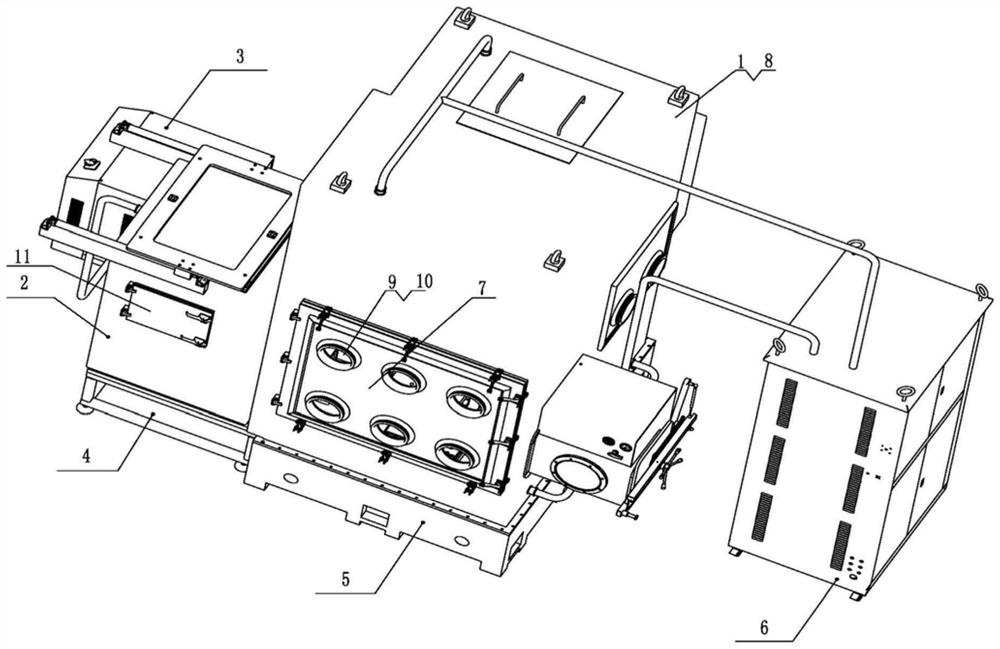
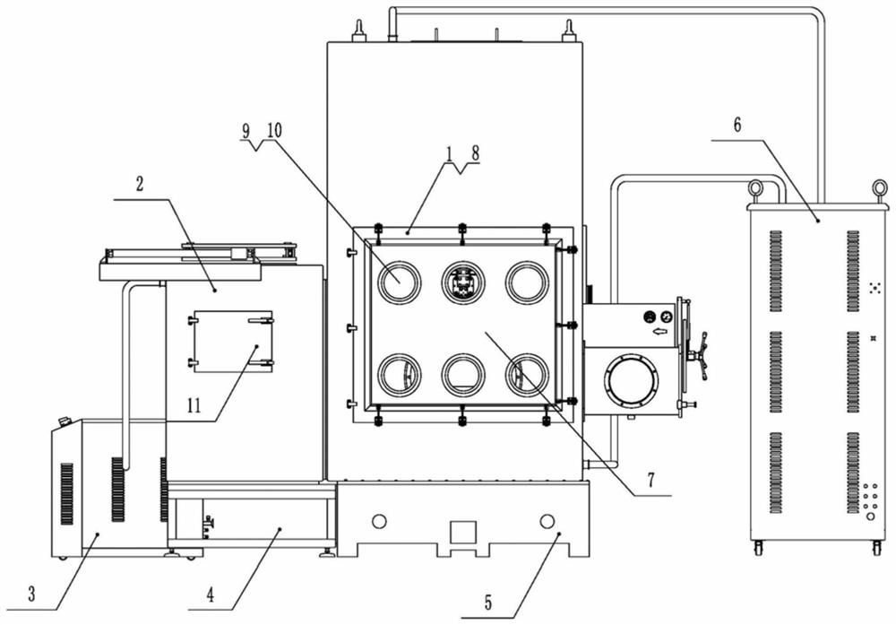
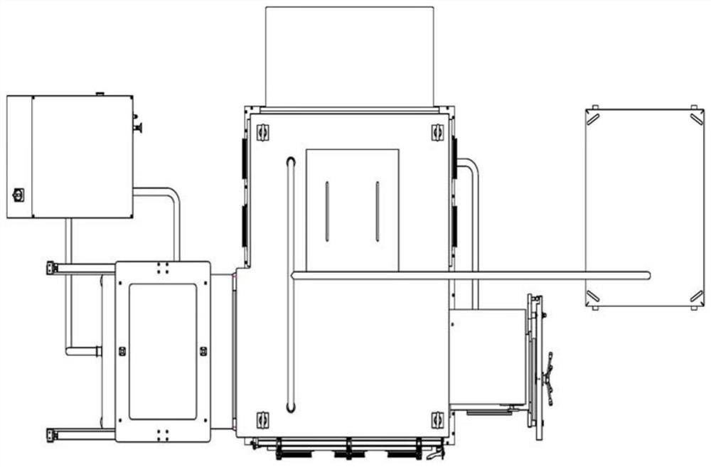
[0123] Figure 1 to Figure 4 The basic structure of the metal additive manufacturing system is given:

[0124] The system includes an equipment sealing box 1, a workpiece buffering area sealing box 2, a buffering area purifier 3, a buffering area base 4, a first airtight door assembly, an equipment base 5, an equipment purifier 6, and an additive equipment 8;

[0125] The bottom of the equipment sealing box 1 is fixedly installed on the equipment base 5, and a sealing ring is installed between the bottom surface of the equipment sealing box 1 and the top surface of the equipment base 5; the buffer area base 4 is installed on the left side of the equipment base 5, and the workpiece buffer area sealing box 2 is fixed Installed on the base 4 of the buffer area and a sealing ring is installed between the bottom surface of the sealing box 2 of the workpiece buffer area and the top surface of the base 4 of the buffer area; a first sealing door assembly is arranged between the sealin...


PUM


Abstract

The invention relates to a metal additive manufacturing system, which greatly saves the time for filling protective gas and improves the working efficiency of the metal additive manufacturing process. The system includes additive equipment, an equipment sealing box, a first sealing door assembly, a workpiece buffering area sealing box, a buffer area purifier, a buffer area base, an equipment base, and an equipment purifier; the equipment sealing box is fixedly installed on the equipment base; The sealing box of the workpiece buffer area is fixedly installed on the base of the buffer area; the sealing box of the equipment and the sealing box of the workpiece buffering area are connected or isolated through the first sealing door assembly; the front of the sealing box of the equipment is provided with a door, and there are multiple Working holes; operating gloves are installed in each working hole; a movable door is provided on the front of the sealed box in the workpiece buffer area; a workpiece placement platform is installed in the sealed box in the workpiece buffer area; the equipment purifier and the buffer area purifier are respectively sealed with the equipment The box is connected with the sealing box in the workpiece buffer area; the additive equipment is fixedly installed on the equipment base.

Description

technical field [0001] The invention relates to the technical field of metal additive manufacturing, in particular to a metal additive manufacturing system. Background technique [0002] The metal additive manufacturing system is a technology that uses bondable materials such as powdered metal and wire metal to construct objects by layer-by-layer printing. The printed objects are 3D shapes and have different shapes. [0003] Existing metal additive manufacturing machines exist as follows: [0004] (1) The sealed space of the existing metal additive manufacturing system is large, and the metal additive manufacturing system needs to work in the atmosphere of protective gas, so it is often necessary to fill the sealed space of the metal additive manufacturing system with protective gas. The sealing space is large, and it takes a long time to fill the protective gas. After the workpiece is printed, the door needs to be opened. In this way, it takes a long time to fill the prote...

Claims


Application Information

Patent Timeline
Patent Type & Authority Patents(China)
IPC IPC(8): B22F3/00B22F3/105B22F12/00B22F12/50B33Y30/00B22F12/45B22F12/70B22F12/90
CPCB22F3/00B33Y30/00Y02P10/25
Inventor 薛飞吴增峰王俊岭卢秉恒
Owner BEIJING WANWEI ADDITIVE MFG TECH CO LTD
Why Eureka
Try Eureka