Feeding device for automatic tin dipping machine and working method of feeding device

A tin dipping machine and automatic technology, applied in the direction of auxiliary devices, manufacturing tools, metal processing equipment, etc., can solve the problems of human health hazards, low work efficiency, low work efficiency, etc., achieve stable transfer process, improve feeding efficiency, The effect of avoiding damage

Pending Publication Date: 2019-09-20
BENGBU ZHENGYUAN ELECTRONICS TECH
View PDF8 Cites 2 Cited by
  • Summary
  • Abstract
  • Description
  • Claims
  • Application Information

AI Technical Summary

Problems solved by technology

[0004] The purpose of the present invention is to provide a feeding device and working method for an automatic tin dipping machine, to solve the problem that the existing tin dipping machines mainly include manual tin dipping machines and semi-automatic tin dipping machines, so that the tin dipping machines can It is necessary to manually place the workpiece to be processed on the workbench of the tin immersion machine, and then start the tin immersion machine to complete the tin immersion, and its work efficiency is relatively low; the human body is in contact with high-temperature and toxic tin metal for a long time, which brings harm to human health; Some immersion tin machines need to manually take out the processed workpieces from the workbench of the tin immersion machine and store them in the storage box after the work is finished. The process of manual handling is not only low in work efficiency, but also easy to fade the workpieces Or technical problems caused by collision with other workpieces during the stacking process

Method used


Image

  • Feeding device for automatic tin dipping machine and working method of feeding device
  • Feeding device for automatic tin dipping machine and working method of feeding device
  • Feeding device for automatic tin dipping machine and working method of feeding device

Examples


Embodiment Construction

[0033] The technical solutions of the present invention will be clearly and completely described below in conjunction with the embodiments. Apparently, the described embodiments are only some of the embodiments of the present invention, not all of them. Based on the embodiments of the present invention, all other embodiments obtained by persons of ordinary skill in the art without creative efforts fall within the protection scope of the present invention.

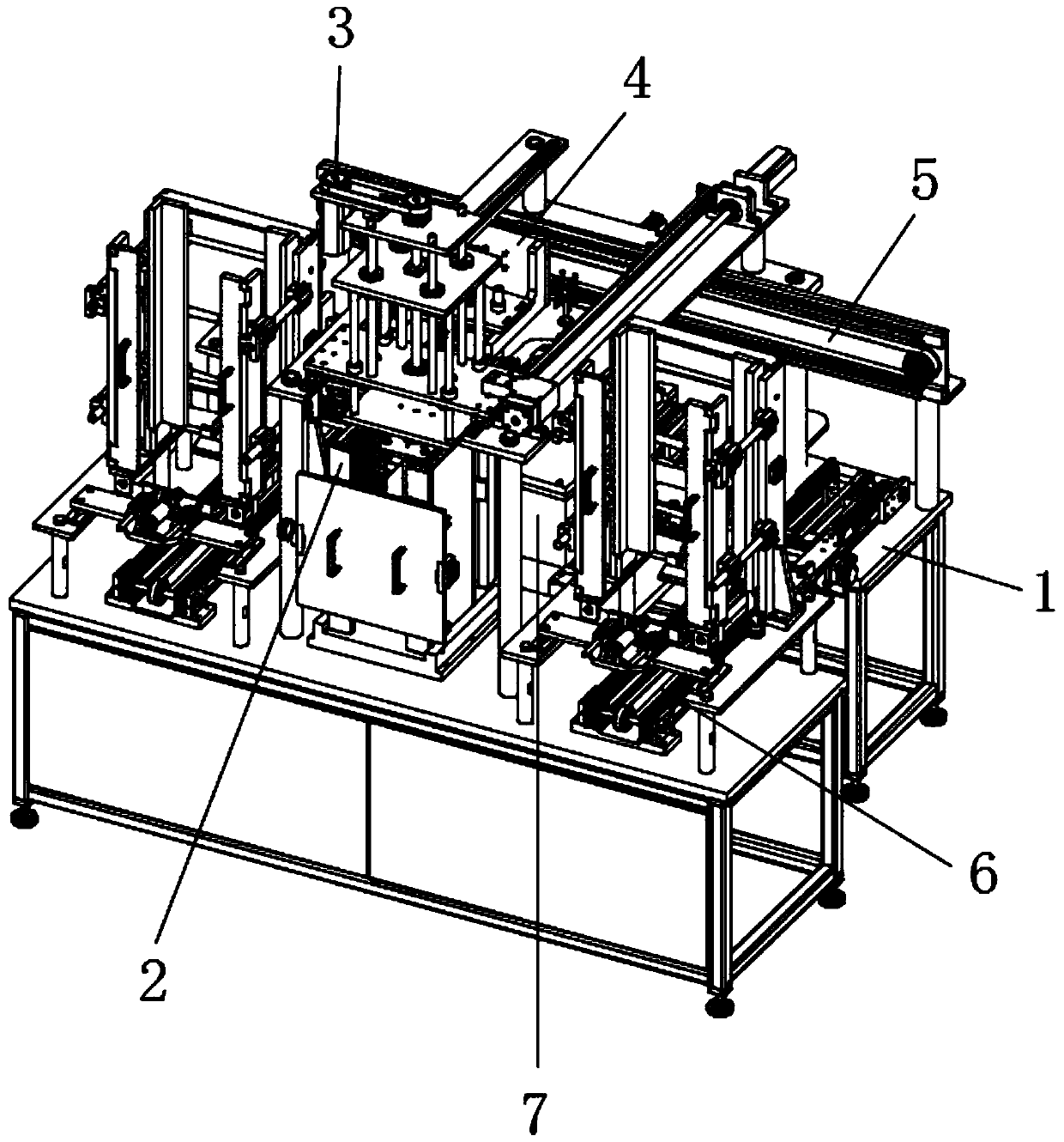
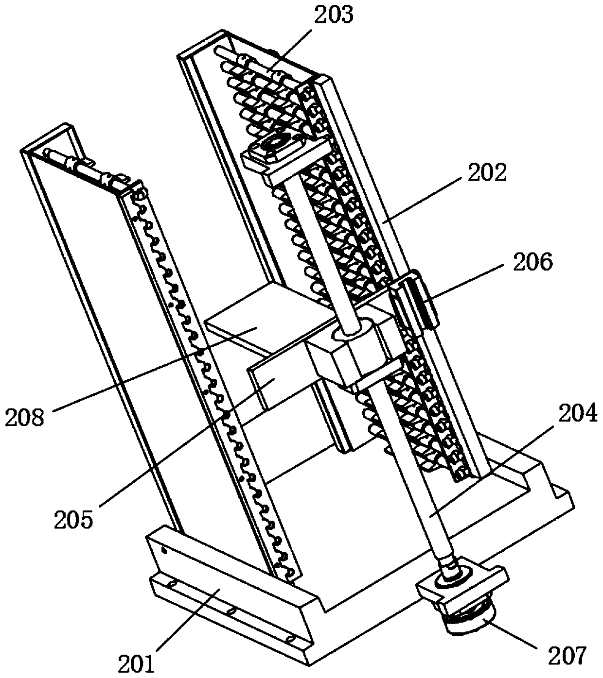
[0034] see Figure 1-6 , a feeding device for an automatic tin dipping machine, comprising: a frame 1, an adsorption mechanism 3 located at one end of the frame 1 for absorbing and retrieving materials, and a transfer mechanism 2 located at the bottom of the adsorption mechanism 3 for feeding , the dipping tin table 7 located in the middle of the frame 1 and the discharge mechanism 6 located at both ends of the tin dipping table 7 and discharging the workpiece, the transfer mechanism 2 includes a base 201, a splint 202, an ...


PUM


Abstract

The invention discloses a feeding device for an automatic tin dipping machine and a working method of the feeding device. A transmission wheel is driven by a second motor to rotate so as to drive a driven wheel to rotate by a first belt; a first screw rod is driven to rotate by the driven wheel, so that a rotating plate is moved above a workpiece placed between two clamping plates, and the workpiece is absorbed by a plurality of sucking discs; and after adsorption, the first screw rod is driven by the second motor to rotate reversely so as to drive the rotating plate to move upwards, and therefore the workpiece is transferred to a tin dipping table by the plurality of sucking discs. As the workpiece is absorbed by the plurality of sucking discs, the workpiece is more stable in the transferring process and is prevented from deformation or falling damage for excessive or less force, and the feeding efficiency is greatly improved; the feeding is completed through the driving of a first motor, so that the transferring process is more stable and efficient, and the collision with other workpieces in the transferring process is avoided; and the whole process is simple to operate and does not need a large amount of labors, and the labor cost and the time cost are greatly reduced.

Description

technical field [0001] The invention relates to the field of feeding devices, in particular to a feeding device for an automatic tin dipping machine and a working method thereof, and belongs to the technical field of application of the feeding device for an automatic tin dipping machine. Background technique [0002] In the field of electronic product processing, various processing equipment are often used, and tin dipping machine is one of the more important equipment. The tin dipping machine is mainly used for tinning the PCB with electronic components inserted, that is, the PCB is placed on the tin surface in the tin furnace to let the liquid tin stick to the insertion hole of the PCB, so that the electronic components are soldered on the PCB. [0003] The existing tin dipping machines mainly include manual tin dipping machines and semi-automatic tin dipping machines, so that the tin dipping machine needs to manually place the workpiece to be processed on the workbench of...

Claims


Application Information

Patent Timeline
Patent Type & Authority Applications(China)
IPC IPC(8): B23K3/08
CPCB23K3/08
Inventor 夏云
Owner BENGBU ZHENGYUAN ELECTRONICS TECH
Why Eureka
Try Eureka