Deflection scanning control method for electron beam welding of dissimilar alloy sheets

A technology of electron beam welding and deflection scanning, applied in electron beam welding equipment, welding equipment, manufacturing tools, etc., can solve the problems of large difference in melting point, deterioration of welding seam quality, and difficulty in ensuring the welding quality of joints, and achieve uniform internal structure. , The effect of good surface forming and low heat input

Inactive Publication Date: 2019-09-20
AVIC BEIJING AERONAUTICAL MFG TECH RES INST
View PDF8 Cites 7 Cited by
  • Summary
  • Abstract
  • Description
  • Claims
  • Application Information

AI Technical Summary

Problems solved by technology

[0005] At present, when electron beam welding is used to weld dissimilar alloy thin plates, the beam position can only be adjusted by optical observation to realize the centering of the weld seam. After centering, the energy input on both sides of the dissimilar alloy is equal. Heat input is difficult to ensure the welding quality of joints
If you want to achieve different energy input on both sides of the dissimilar alloy, you can only fine-tune the relative position of the electron beam spot and the weld seam by mechanical means. Adjusted by optical observation combined with mechanical movement, the heat input ratio cannot be precisely controlled and distributed, resulting in a decrease in weld quality

Method used


Image

  • Deflection scanning control method for electron beam welding of dissimilar alloy sheets
  • Deflection scanning control method for electron beam welding of dissimilar alloy sheets

Examples


Embodiment Construction

[0021] Embodiments of the present invention will be further described in detail below in conjunction with the accompanying drawings and examples. The detailed description and accompanying drawings of the following embodiments are used to illustrate the principles of the present invention, but cannot be used to limit the scope of the present invention, that is, the present invention is not limited to the described embodiments, without departing from the spirit of the present invention Any modification, substitution and improvement of parts, components and connection methods are covered under.

[0022] It should be noted that, in the case of no conflict, the embodiments in the present application and the features in the embodiments can be combined with each other. The present application will be described in detail below with reference to the accompanying drawings and embodiments.

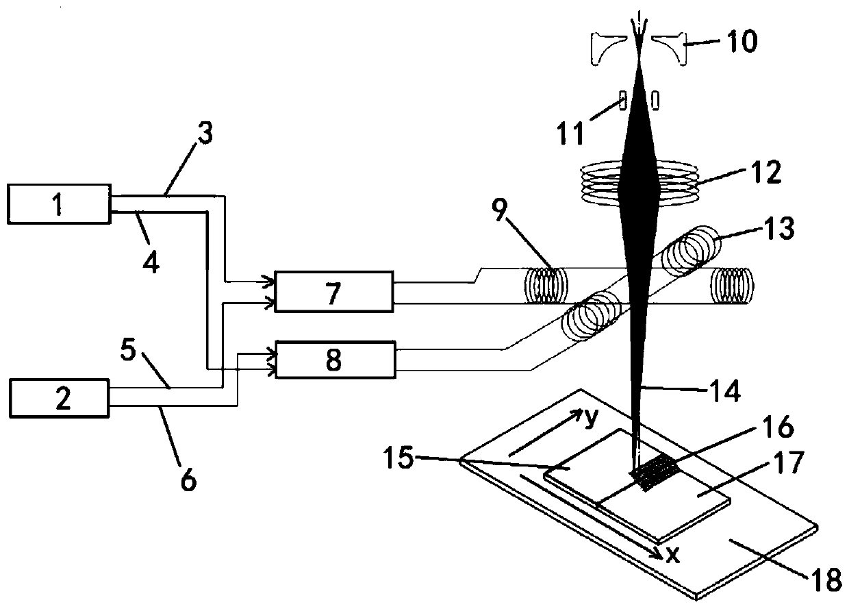
[0023] figure 1 It is a schematic diagram of the application scene of a deflection scanning con...


PUM


Abstract

The invention relates to a deflection scanning control method for electron beam welding of dissimilar alloy sheets. The method comprises steps as follows: an electrified defection coil is arranged at the output end of an electron beam channel and at the output side of a focusing coil of an electronic gun, so that focused electron beams produce deflection scanning beam currents under the function of Lorentz force in a magnetic field; by controlling the magnitude of electricity input into the deflection coil, deflection scanning parameters of the electron beams can be controlled, electron beam spots with heat input energy in Gaussian distribution can be obtained, when the dissimilar alloy sheets are subjected to electron beam welding, heat input energy of the electron beam spots acting on the alloy sheet with a low melting point and that of the electron beam spots acting on the alloy sheet with a high melting point are P0 and P1 respectively, and P0 is smaller than P1. With arrangement of the electrified deflection coil, a deflection scanning magnetic field can be controlled to control offset of the electron beams accurately, more energy is input to the side with a high melting point, less energy is input to the side with a low melting point, so that heat input can be controlled accurately during welding, and welded joints with better performance can be obtained.

Description

technical field [0001] The invention relates to the technical field of electron beam welding, in particular to a deflection scanning control method for electron beam welding of dissimilar alloy thin plates. Background technique [0002] With the rapid development of aviation, aerospace, microelectronics and national defense industries, more and more stringent requirements are put forward for the service performance of components. Components made of a single material can no longer meet the service conditions under complex working conditions. In order to meet the development needs of lightweight components, structural and functional integration, and low-cost design and manufacture, the development from a single alloy to multiple alloy composite components has become a new application. trend. To maximize the performance advantages of dissimilar materials. [0003] For the welding of dissimilar materials, due to the differences in physical and chemical properties and metallurg...

Claims


Application Information

Patent Timeline
Patent Type & Authority Applications(China)
IPC IPC(8): B23K15/00
CPCB23K15/00B23K15/0013
Inventor 桑兴华曲树平许海鹰杨波付鹏飞张红玉路开通
Owner AVIC BEIJING AERONAUTICAL MFG TECH RES INST
Why Eureka
Try Eureka