Printing rubber roller

A technology for printing rubber rollers and installation rollers, which is applied in printing, printing machines, rotary printing machines, etc., can solve the problems of lower yield, increased embossing difficulty, embossing, etc., and achieve the goal of increasing yield and printing yield Effect

Active Publication Date: 2019-09-20
岳阳市大地印务有限公司
View PDF9 Cites 1 Cited by
  • Summary
  • Abstract
  • Description
  • Claims
  • Application Information

AI Technical Summary

Problems solved by technology

The invention is mainly used to solve the problem that the printing rubber rollers in the prior art cannot imprint the fabric at the first time after dyeing is completed, which leads to a great increase in the difficulty of fast drying and embossing of the dye, that is, a greatly reduced yield

Method used


Image

  • Printing rubber roller
  • Printing rubber roller
  • Printing rubber roller

Examples


Embodiment Construction

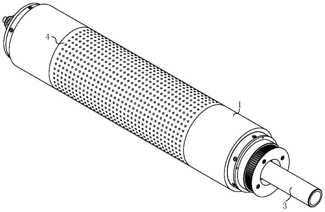
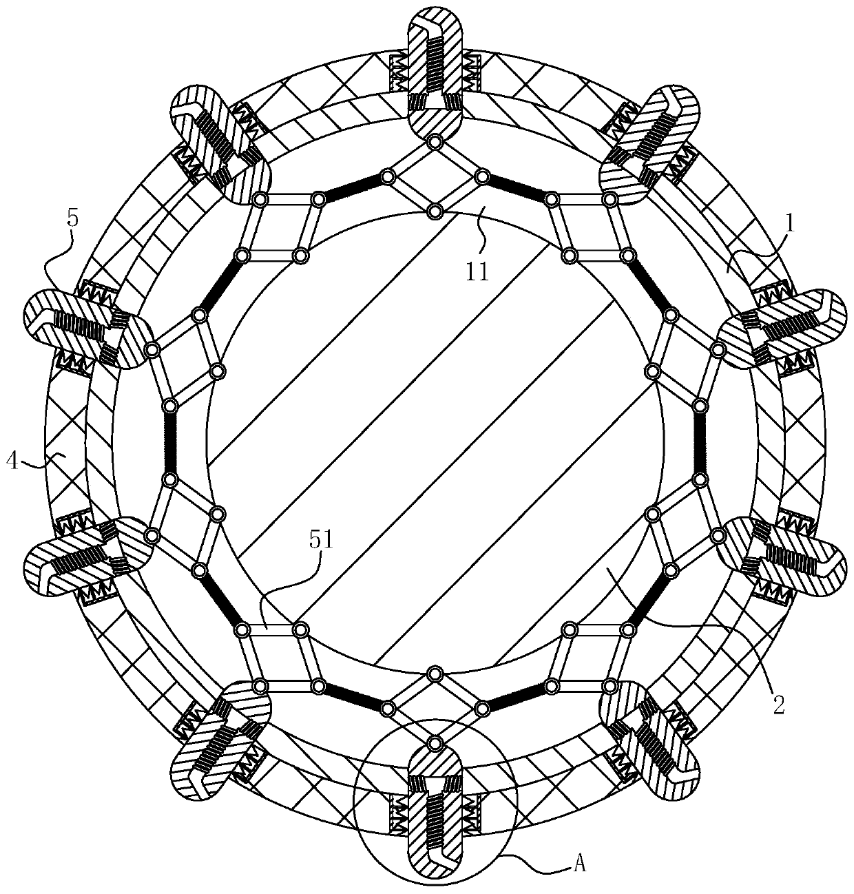
[0018] use Figure 1-Figure 3 A rubber printing roller according to one embodiment of the present invention will be described below.

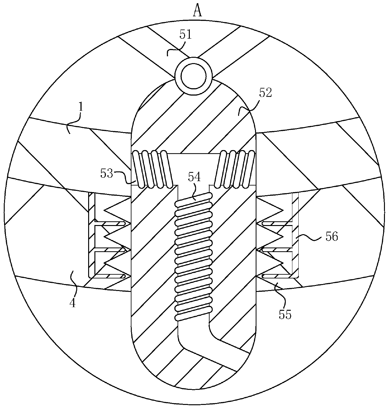
[0019] Such as Figure 1-Figure 3 As shown, a printing rubber roller according to the present invention includes a mounting roller 1, a braking roller 2, an infusion tube 3, a rubber ring 4 and a spraying mechanism 5, and the outer side of the braking roller 2 is fixedly installed with a mounting roller 1 A liquid storage chamber 11 is provided between the installation roller 1 and the brake roller 2, the right end of the installation roller 1 is fixedly connected with an infusion tube 3, and a rubber ring 4 is fixedly embedded in the middle outer end wall of the installation roller 1; The infusion tube 3 communicates with the liquid storage chamber 11; the spraying mechanism 5 is provided in the liquid storage chamber 11; the spraying mechanism 5 includes a hinged frame 51, a sliding rod 52 and a liquid flow hole 53; the inner end of the hing...


PUM


Abstract

The invention belongs to the field of printing equipment accessories, and particularly relates to a printing rubber roller. The printing rubber roller comprises a installation roller, a brake roller, a liquid conveying pipe, a rubber ring and a spraying mechanism, wherein the installation roller is fixedly arranged on the outer side of the brake roller; a liquid storage cavity is formed in a position between the installation roller and the brake roller; the liquid conveying pipe is fixedly connected to the right end of the installation roller; the rubber ring is fixedly embedded in the outer end wall of the middle of the installation roller; the liquid conveying pipe communicates with the liquid storage cavity; the spraying mechanism is arranged in the liquid storage cavity; the spraying mechanism comprises a hinged frame, a sliding rod and a liquid flowing hole; the inner end of the hinged frame is uniformly and fixedly arranged on the outer surface of the brake roller; the hinged frame is provided with a torsion spring; and the outer end of the hinged frame is fixedly connected with the sliding rod. The printing rubber roller is mainly used for solving the problems that a printing rubber roller in the prior art is not able to imprint fabric at the first time when the fabric is dyed to result in increasing the imprinting difficulty because dye is dried and solidified quickly, thereby reducing the yield is greatly.

Description

technical field [0001] The invention belongs to the field of printing equipment accessories, in particular to a printing rubber roller. Background technique [0002] The rubber roller is a roller-shaped product made of metal or other materials as the core and covered with rubber by vulcanization. It can be divided into papermaking rubber rollers, printing and dyeing rubber rollers, printing rubber rollers, hulling rubber rollers, and metallurgical rubber rollers. And mimeograph rubber rollers, etc. The rubber rollers are generally composed of outer layer rubber, hard rubber layer, metal core, roll neck and vent holes. Vulcanization tank vulcanization and surface processing and other processes. Rubber rollers are mainly used in papermaking, printing and dyeing, printing, food processing, metallurgy, plastic processing, etc., and printing rubber rollers can be divided into two categories: hard rollers and soft rollers, which are used in printing machinery as embossing, ink ad...

Claims


Application Information

Patent Timeline
Patent Type & Authority Applications(China)
IPC IPC(8): B41F13/08
CPCB41F13/08
Inventor 周宇凡许智勇程慧玲
Owner 岳阳市大地印务有限公司
Why Eureka
Try Eureka