Tire bead structure of tires

A bead and tire technology, applied in tire parts, bead, transportation and packaging, etc., can solve the problems of shortening tire bearing capacity and service life, achieve balanced stress and strain distribution, reasonable physical property matching, and reduce heat generation. Effect

Pending Publication Date: 2019-09-20
HEFEI WANLI TIRE CO LTD
View PDF0 Cites 1 Cited by
  • Summary
  • Abstract
  • Description
  • Claims
  • Application Information

AI Technical Summary

Problems solved by technology

Among them, since there are only two types of rubber materials for the apex rubber setting, when the load is sustained or instantaneously too large, the overall hardness and rigidity of the bead part exceed the limit, and the stress and strain are too concentrated on the end points of the carcass and steel wire reinforcement. The flexural deformation of the tire bead, the rubber at the carcass and the end of the steel wire reinforcement generate heat, which shortens the load-carrying capacity and service life of the tire

Method used


Image

  • Tire bead structure of tires
  • Tire bead structure of tires

Examples


Embodiment 1

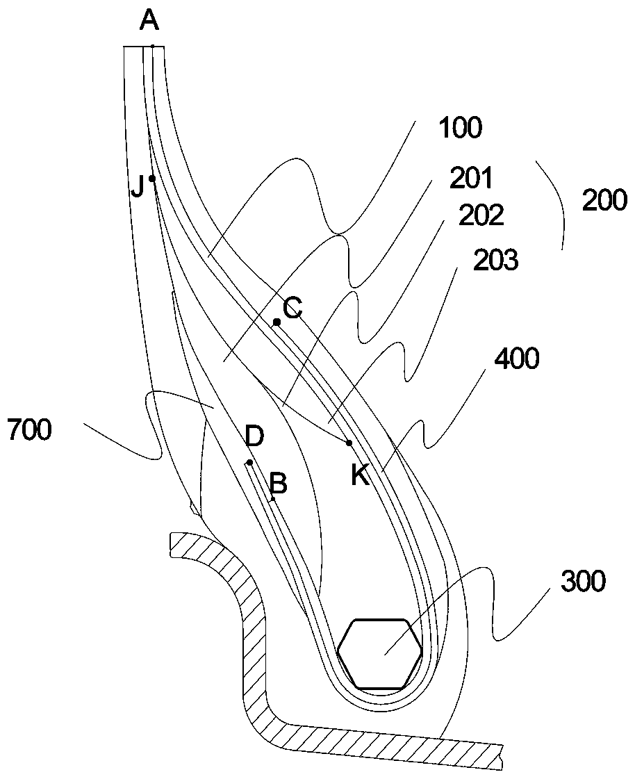
[0023] Please refer to this example figure 1

[0024] A tire bead structure, the bead includes a carcass 100, a bead core and sidewalls, the carcass 100 turns up around the bottom of the bead core to the outside of the bead core, the bead It also includes the first steel wire reinforcement layer 400 and transition glue 700;.

[0025] The bead core also includes a bead ring 300 and an apex rubber 200; the first steel wire reinforcement layer 400 wraps around the bottom of the bead ring 300 on the outside of the carcass 100; the transition rubber 700 is located Above the outer edge of the carcass 100 and between the apex 200 and the sidewall.

[0026] The inner endpoint of the carcass 100 is point A, the outer endpoint is point B, the outer endpoint of the first steel wire reinforcement layer 400 is point D, and the inner endpoint is point C;

[0027] The height difference between the outer end point D of the first steel wire reinforcement layer 400 and the outer end point B ...

Embodiment 2

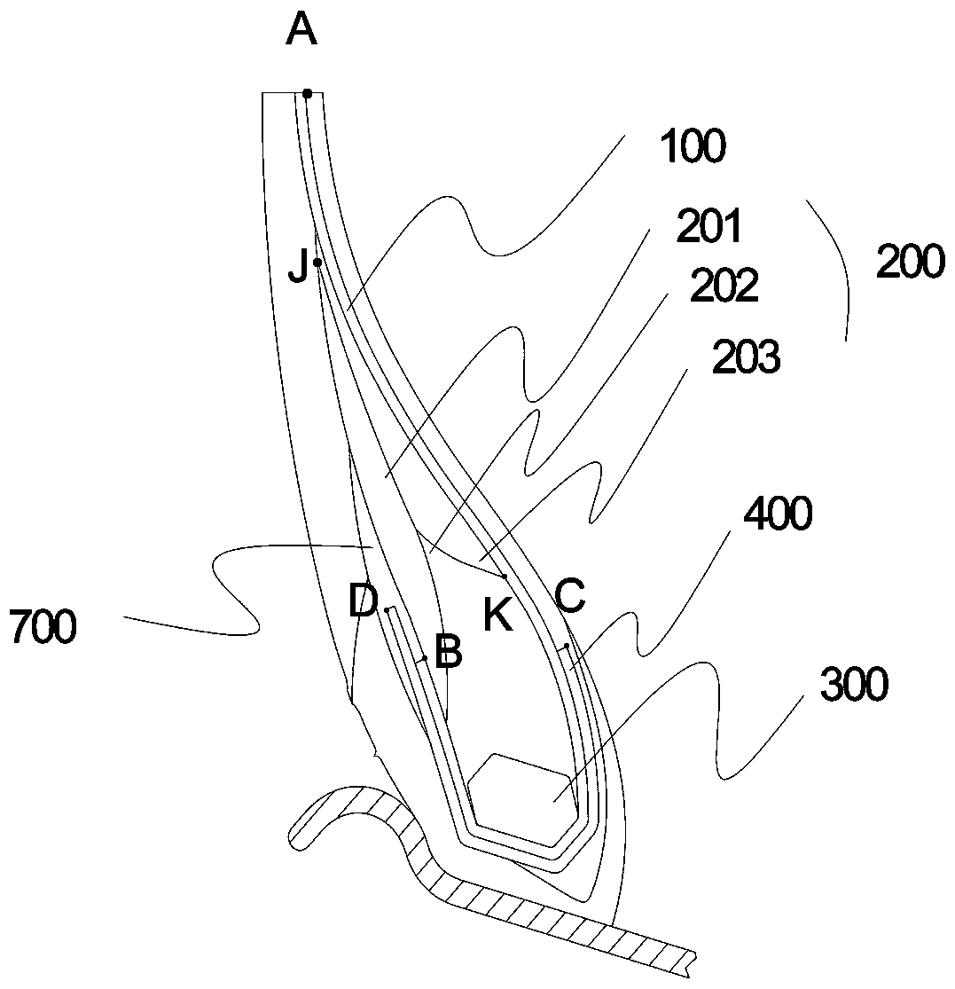
[0043] Please refer to this example figure 2

[0044] A tire bead structure, the bead includes a carcass 100, a bead core and sidewalls, the carcass 100 turns up around the bottom of the bead core to the outside of the bead core, the bead It also includes the first steel wire reinforcement layer 400 and the transition glue 700;

[0045] The bead core also includes a bead ring 300 and an apex rubber 200; the first steel wire reinforcement layer 400 wraps around the bottom of the bead ring 300 on the outside of the carcass 100; the transition rubber 700 is located Above the outer edge of the carcass 100 and between the apex 200 and the sidewall.

[0046] The inner endpoint of the carcass 100 is point A, the outer endpoint is point B, the outer endpoint of the first steel wire reinforcement layer 400 is point D, and the inner endpoint is point C;

[0047] The height difference between the outer endpoint D of the first steel wire reinforcement layer 400 and the outer endpoint ...


PUM


Abstract

The invention belongs to the tire technology field, and particularly relates to a tire bead structure of tires. The tire bead structure of the tires comprises a tire body, a tire bead core and a tire sidewall, wherein the tire body bypasses the bottom of the tire bead core and is reversely wrapped around the outer side of the tire bead core. The tire bead structure of the tires further comprises a first steel wire reinforcement layer and transition type glue. The tire bear core further comprises a steel wire ring and an apex strip. The first steel wire reinforcement layer bypasses the bottom of the steel wire ring and is wrapped around the outer side of the tire body, and the transition type glue is located above the outer endpoint of the tire body and between the apex strip and the tire sidewall. The tire bead structure of the tires has the advantages that compared with the prior art, stress-strain transition among adjacent materials is balanced, physical property matching among the materials is reasonable, and simultaneously the transition type glue is added, stress-strain equilibrium distribution on the endpoint of a steel wire is achieved, stress-strain concentration is avoided, heat generation amount of the tire bead structure is reduced, and therefore carrying capacity of the tires is improved, and use life of the tires is prolonged.

Description

technical field [0001] The invention belongs to the technical field of tires, and in particular relates to a tire bead structure. Background technique [0002] The bead, also known as the bead, refers to the part where the tire is installed on the rim, and is composed of a bead core, a reinforcing layer, a carcass, and a sidewall. It can bear the tensile force caused by internal pressure, and at the same time, it can overcome the lateral force of the tire when it is turning, so that the outer tire will not come out of the rim. Therefore, it must have high strength, and the structure should be tight and firm, and it should not be easily deformed. [0003] In the prior art, the bead includes a bead core, a reinforcing layer and a carcass, the bead core includes a bead ring and an apex, and the reinforcing layer extends from the axially inner side of the apex to the axially outer side of the apex, And it is wrapped together with the carcass on the steel traveler and the end o...

Claims


Application Information

Patent Timeline
Patent Type & Authority Applications(China)
IPC IPC(8): B60C15/00B60C15/04B60C15/05B60C15/06
CPCB60C15/0009B60C15/04B60C15/05B60C15/0607B60C2015/042
Inventor 陈佛国王海洋付波涛辛飞飞尹徐影
Owner HEFEI WANLI TIRE CO LTD
Why Eureka
Try Eureka