
Stainless steel cloth guide roller of dyeing and finishing mechanism

A technology of stainless steel and fabric guide rollers, which is applied in the directions of winding strips, thin material handling, transportation and packaging, etc. It can solve the problems of folding and rolling, affecting the normal delivery of cloth, and misalignment of cloth, so as to ensure winding and smoothing Effect

Active Publication Date: 2019-09-20
海宁鑫港源纺织品有限公司
View PDF7 Cites 3 Cited by
  • Summary
  • Abstract
  • Description
  • Claims
  • Application Information

AI Technical Summary

Problems solved by technology

[0006] The present invention can solve the problem that in the process of conveying and smoothing the cloth by the existing cloth guide roller, the cloth on both sides of the cloth guide roller passes through due to the different horizontal forces under the action of the traction and winding equipment. The deflection causes the dislocation of the cloth in the dyeing and finishing and winding in the later stage, resulting in uneven dyeing and finishing and dislocation of the winding; and the cloth at the lower end of the pressure roller is caused by the action of the winding equipment during the rolling process of the cloth guide roller. The size of the squeezed force is different, resulting in the blockage of the cloth, which will seriously cause the cloth to be folded and rolled, and even affect the normal transportation of the cloth.

Method used


Image

  • Stainless steel cloth guide roller of dyeing and finishing mechanism
  • Stainless steel cloth guide roller of dyeing and finishing mechanism
  • Stainless steel cloth guide roller of dyeing and finishing mechanism

Examples

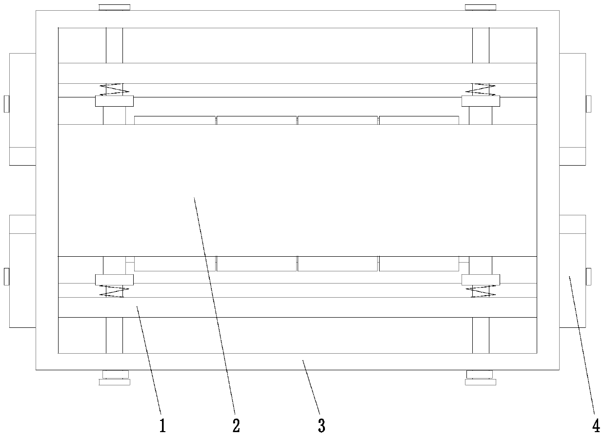
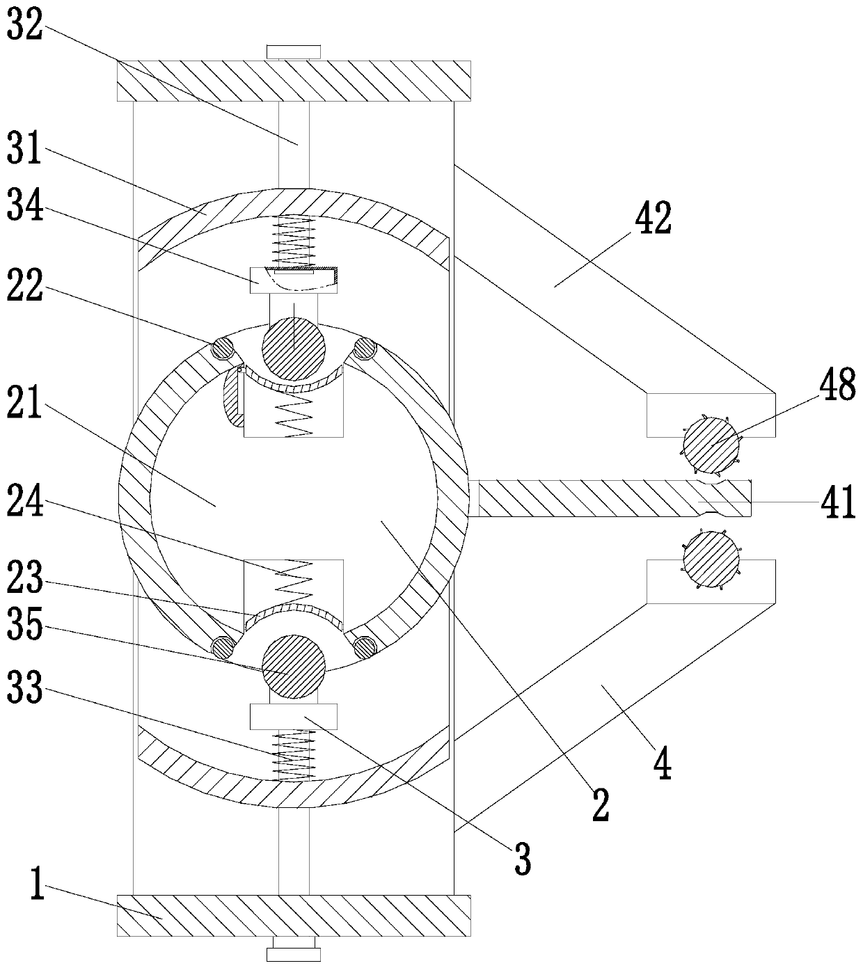

Embodiment Construction

[0025] Embodiments of the present invention will be described below with reference to the drawings. In the process, in order to ensure the clarity and convenience of illustration, we may exaggerate the width of the lines or the size of the constituent elements in the diagram.

[0026] In addition, the following terms are defined based on the functions in the present invention, and may be different according to the user's or operator's intention or practice. Therefore, these terms are defined based on the entire content of this specification.

[0027] like Figure 1 to Figure 5 As shown, a stainless steel fabric guide roller for dyeing and finishing machinery includes an outer frame 1, an auxiliary unit 2, a flattening unit 3 and a tensioning unit 4; A flattening unit 3 is arranged symmetrically up and down inside, and a tensioning unit 4 is arranged on the outer wall of the rear end of the outer frame 1; wherein:

[0028] The auxiliary unit 2 includes an auxiliary cylinder ...


PUM


Abstract

The invention provides a stainless steel cloth guide roller of a dyeing and finishing mechanism. The stainless steel cloth guide roller comprises an outer frame, an assisting unit, flattening units and a tensioning unit, wherein the assisting unit is arranged in the middle part of the outer frame; the flattening units are symmetrically arranged at the inner top and bottom of the outer frame; and the tensioning unit is arranged on the outer wall of the rear end of the outer frame. The stainless steel cloth guide roller of the dyeing and finishing mechanism solves the problems such as that a cloth bears different transverse power under the effect of a pulling coiling device while an existing cloth guide roller is used for conveying and flattening the cloth, thus the clothes passing through two sides of the cloth guide roller are deviated, and the cloth is staggered in later dyeing and finishing process, and as a result, uniform dyeing and finishing cannot be realized, and staggering occurs in the coiling process; the cloth at the lower end of a cloth pressing roller bears different extruding pressure under the effect of the coiling device while being rolled and pressed through the cloth guide roller, thus the cloth is blocked, and the cloth is folded and rolled in case of serious blocking, and even the normal conveying of the cloth is influenced.

Description

technical field [0001] The invention relates to the technical field of textile machinery, in particular to a stainless steel cloth guide roller of a dyeing and finishing machine. Background technique [0002] Cloth guide roller is an essential part of textile printing and dyeing equipment, used to guide and transport fabrics, the traditional cloth guide roller device is directly connected to the printing and dyeing machine or textile machine, generally composed of several cloth guide rollers, its practical quantity The cloth guide roller is set according to the size of the machine and the process requirements, but the traditional cloth guide roller mainly has the following problems during use: [0003] 1. During the process of conveying and smoothing the cloth by the cloth guide roller, due to the different transverse force received by the cloth under the action of the traction and winding equipment, the cloth on both sides of the cloth guide roller passing through is deflec...

Claims


Application Information

Patent Timeline
IPC IPC(8): B65H23/26B65H27/00
CPCB65H23/26B65H27/00
Inventor 倪新贺张皖龙张伟健
Owner 海宁鑫港源纺织品有限公司
Learn More