
Road marking equipment with circulated stirring function

A technology of circulating stirring and scribing equipment, which is applied in the direction of roads, roads, road repairs, etc. It can solve the problems of easy sedimentation of paint, inconvenient adjustment of nozzle position, and difficulty in meeting people's use needs, so as to improve stirring efficiency, prevent paint sedimentation, Evenly mixed paint effect

Inactive Publication Date: 2019-09-20
赣州市兴顺辉科技有限公司
View PDF13 Cites 5 Cited by
  • Summary
  • Abstract
  • Description
  • Claims
  • Application Information

AI Technical Summary

Problems solved by technology

[0003] During the working process of the existing road marking equipment, the paint is easy to precipitate, and the position of the nozzle is inconvenient to adjust, which is difficult to meet people's needs

Method used


Image

  • Road marking equipment with circulated stirring function
  • Road marking equipment with circulated stirring function
  • Road marking equipment with circulated stirring function

Examples


Embodiment 1

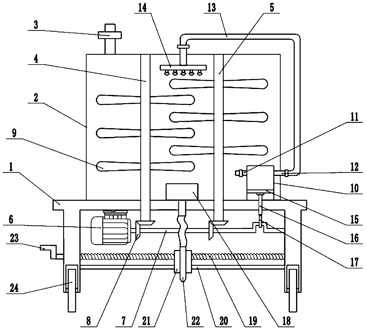
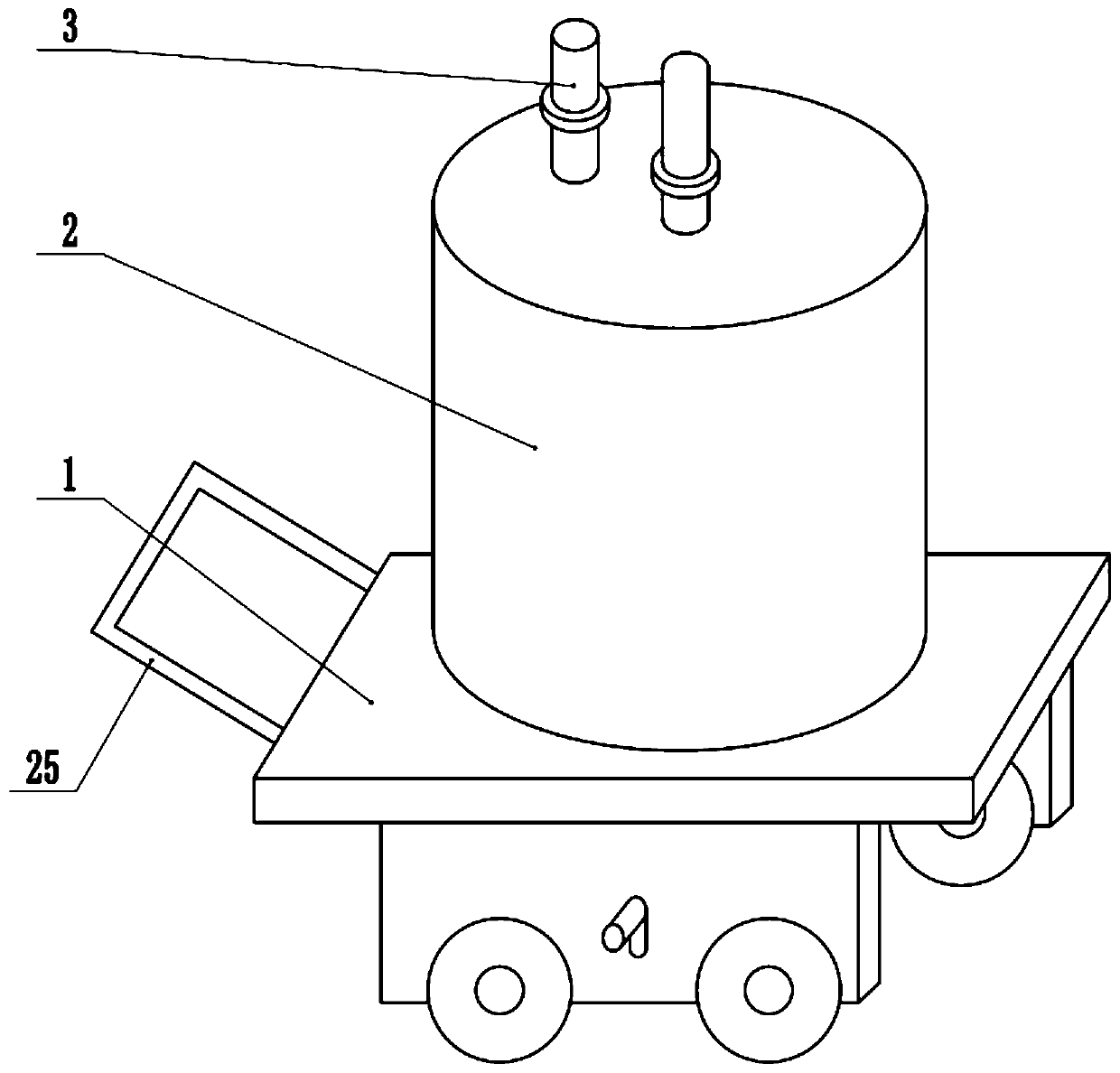
[0022] see Figure 1-3 , in an embodiment of the present invention, a road marking device with a circulating stirring function, comprising a fixed frame 1, a tank body 2, a water pump 18 and a spray gun 22, the upper surface of the fixed frame 1 is fixedly connected with a tank body 2, and the tank body A filling pipe 3 is installed on the top of the tank 2, and the filling pipe 3 communicates with the tank body 2. The paint is injected into the tank body 2 through the filling pipe 3. The bottom of the fixed frame 1 is fixedly connected with a motor 6, and the shaft end of the motor 6 is fixed. A crankshaft 7 is connected, and the end of the crankshaft 7 is rotatably connected with the fixed frame 1 .

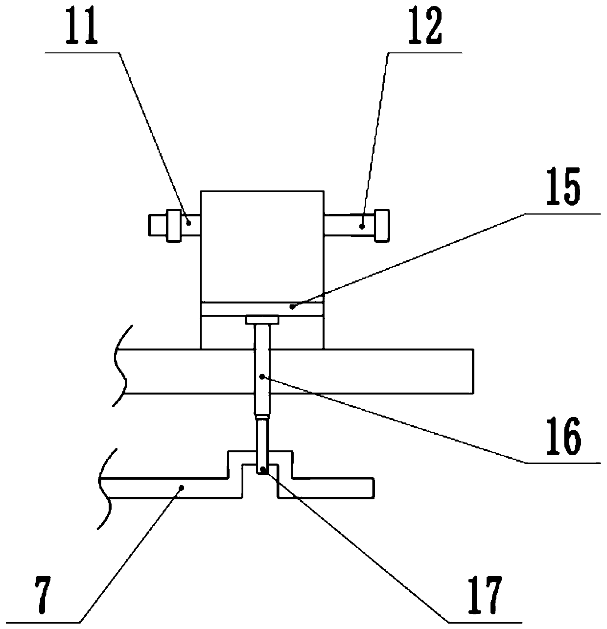
[0023] The inside of the tank body 2 is equipped with a circulation assembly, the circulation assembly includes a piston cylinder 10, a nozzle 14, a piston plate 15, a movable column 16 and a connecting rod 17, the inside of the tank body 2 is equipped with a piston cylinder 10...

Embodiment 2

[0026] On the basis of embodiment 1, a stirring mechanism is installed inside the tank body 2, and the stirring mechanism includes a left stirring shaft 4, a right stirring shaft 5 and a stirring blade 9, and the upper and lower ends of the left stirring shaft 4 and the right stirring shaft 5 are respectively connected to the The top and bottom of the tank body 2 are rotationally connected, the lower ends of the left stirring shaft 4 and the right stirring shaft 5 pass through the fixing frame 1 and extend to the bottom of the fixing frame 1, and the lower ends of the left stirring shaft 4 and the right stirring shaft 5 pass through the bevel gear respectively. The group 8 is connected with the crankshaft 7, and the left stirring shaft 4 and the right stirring shaft 5 are interlaced with the stirring blades 9. When the motor 6 is running, the crankshaft 7 is driven to rotate, thereby driving the left stirring shaft 4 and the right stirring shaft 5 to rotate. 9 Stir the paint in...


PUM


Abstract

The invention relates to the field of road and bridge construction equipment, in particular to road marking equipment with a circulated stirring function. The road marking equipment comprises a fixing frame, a tank body, a water pump and a spray gun, wherein the tank body is fixedly connected to the upper surface of the fixing frame, a motor is fixedly connected to the bottom of the fixing frame, a crankshaft is fixedly connected to the shaft extension end of the motor, a circulation assembly is arranged inside the tank body, a water pump is arranged inside the tank body, a screw rod is installed below the fixing frame, a guide rod is arranged below the screw rod, a slide block is arranged on the screw rod in a sleeving mode, a spray gun is arranged on the slide block, the spray gun is in communication with a water outlet of the water pump through a telescopic hose, and a stirring mechanism is arranged inside the tank body. The stirring mechanism is used for stirring coating in the tank body, so that the coating is more uniformly mixed, and coating precipitation is prevented; circulated stirring of the coating is realized by arranging the circulating assembly, so that the coating is more uniformly mixed, and the stirring efficiency is further improved; and in the spraying process, the position of the spray gun can be adjusted according to actual spraying requirements.

Description

technical field [0001] The invention relates to the field of road and bridge construction equipment, more specifically, a road marking equipment with a circulating stirring function. Background technique [0002] Road markings are also called road markings. Refers to the signs on the road surface that use lines, arrows, text, facade marks, raised road signs and contour marks to convey traffic information such as guidance, restrictions, and warnings to traffic participants. Its function is to control and guide traffic, and it can be used in conjunction with signs or alone. Road marking is mainly drawn on the road surface, which is exposed to the sun, rain, wind, snow and ice, and is subjected to the impact and wear of vehicles, so there are strict requirements on its performance. It is a safety sign and a "language" in road traffic. [0003] During the working process of the existing road marking equipment, the paint is easy to precipitate, and the position of the nozzle i...

Claims


Application Information

Patent Timeline
Patent Type & Authority Applications(China)
IPC IPC(8): E01C23/22
CPCE01C23/22E01C23/227
Inventor 陈万青
Owner 赣州市兴顺辉科技有限公司
Learn More