Comprehensive pipe rack foundation pit support replacement device and mounting method thereof

A technology of comprehensive pipe gallery and foundation pit, which is applied in excavation, infrastructure engineering, water conservancy engineering and other directions, can solve the problems of backfilling and compaction increasing the difficulty of operation, long construction period for foundation pit replacement, affecting the construction of subsequent processes, etc. The construction period, installation and operation are simple, and the work effect is small.

Active Publication Date: 2019-09-20
CHINA FIRST METALLURGICAL GROUP
View PDF1 Cites 1 Cited by
  • Summary
  • Abstract
  • Description
  • Claims
  • Application Information

AI Technical Summary

Problems solved by technology

The first construction period of this method is longer, which affects the construction progress; after the second reinforced concrete slab is replaced, it will increase the difficulty of subsequent backfilling and compaction
[0003] In order to overcome the above technical problems, the present invention intends to design a foundation pit replacement device and its installation method for a comprehensive pipe gallery, which provides a solution for solving the long construction period of foundation pit replacement and affecting the construction of subsequent processes

Method used


Image

  • Comprehensive pipe rack foundation pit support replacement device and mounting method thereof
  • Comprehensive pipe rack foundation pit support replacement device and mounting method thereof
  • Comprehensive pipe rack foundation pit support replacement device and mounting method thereof

Examples


Embodiment Construction

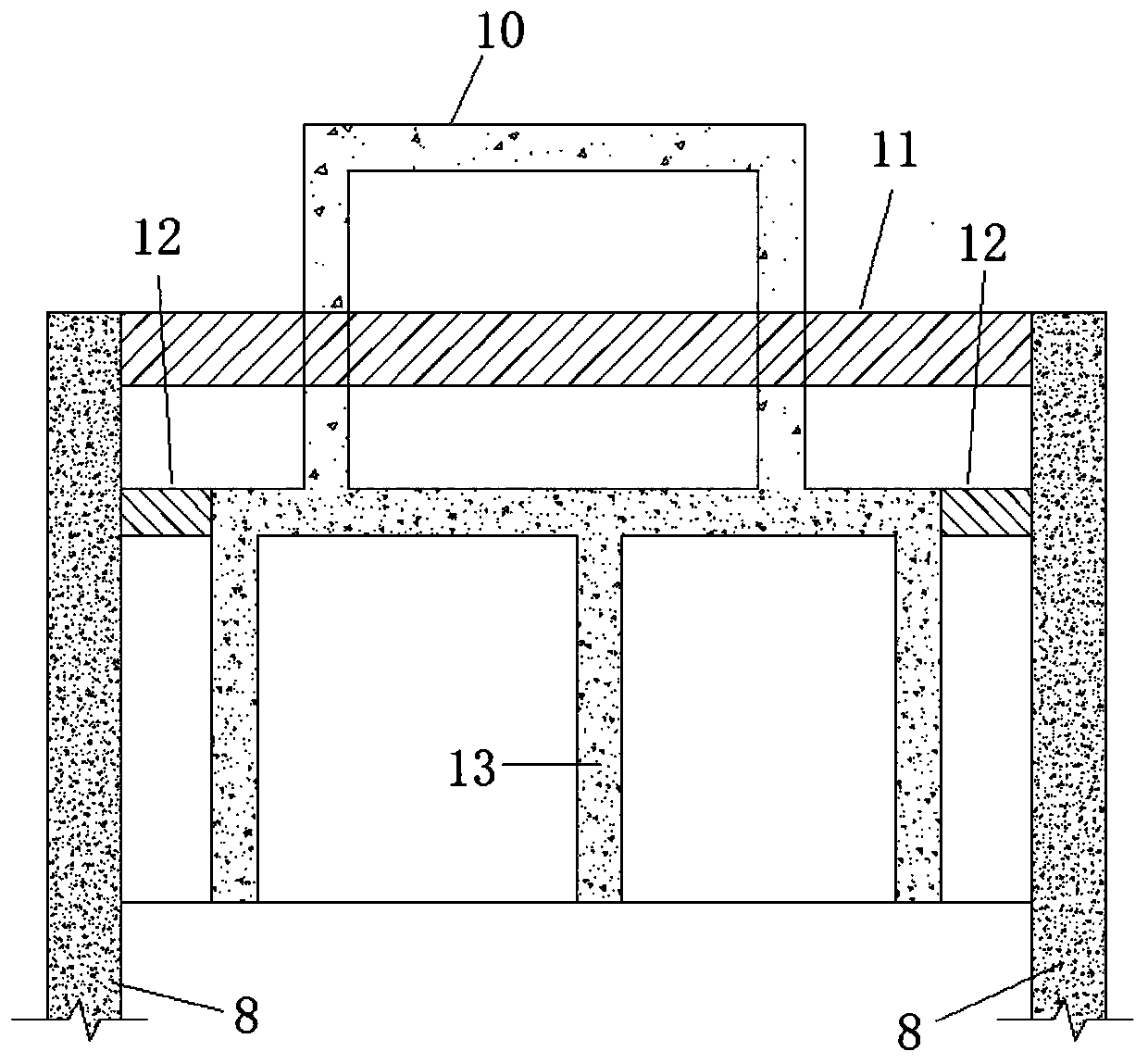
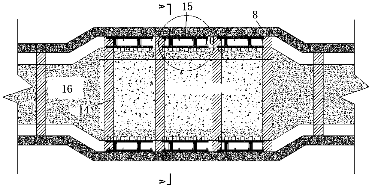
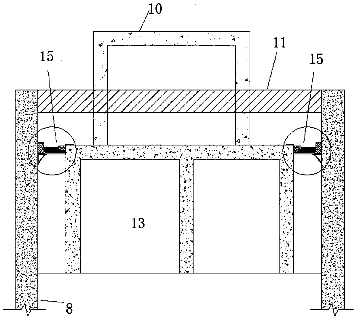
[0033] Below by embodiment, in conjunction with accompanying drawing, the technical scheme of the present invention is described further specifically, as Figure 2-5 As shown, the device is composed of I-beam 1, cushion block 2, pipe gallery purlin 3, pile purlin 4, Z-shaped frame 5, purlin bracket 6, and L-shaped cushion block 7. First, install the purlin bracket 6 on the support pile; the second step is to fix the pile purlin 4 on the purlin bracket 6; the third step is to place one end of the Z-shaped frame 5 on the roof of the comprehensive pipe gallery, and fix the other end on the Purlin bracket 6; the fourth step is to place the L-shaped pad 7 at the corner of the roof of the comprehensive pipe gallery. The purpose of the L-shaped pad 7 is to transfer the load of the purlin 3 to the comprehensive pipe gallery evenly, avoid The load pressure is too concentrated; the L-shaped pad 7 can be densely arranged according to the load; the fifth step is to fix the purlin 3 of the...


PUM


Abstract

The invention provides a comprehensive pipe rack foundation pit support replacement device. The comprehensive pipe rack foundation pit support replacement device comprises a support replacement device body located between a foundation pit support pile and a comprehensive pipe rack main body structure, and is characterized in that the support replacement device body comprises an enclosing purlin bracket mounted on the inner side of the support pile, a Z-shaped frame mounted on a roof of a pipe rack, pile enclosing purlin and pipe rack enclosing purlin, wherein the pile enclosing purlin and the pipe rack enclosing purlin are fixed to the enclosing purlin bracket and the Z-shaped frame correspondingly; and I-shaped steel is arranged between the pile enclosing purlin and the pipe rack enclosing purlin, one end of an L-shaped frame is placed on the roof of the comprehensive pipe rack, and the other end of the L-shaped frame is fixed to the upper part of a horizontal supporting plate of the enclosing purlin bracket. The comprehensive pipe rack foundation pit support replacement device is simple in structure, easy and convenient to operate, and capable of being quickly mounted and dismounted, being reutilized and achieving the purposes of saving materials and effectively shortening the construction period; and meanwhile the space can also be saved, and convenient conditions are provided for backfilling of fertilizer grooves between the comprehensive pipe rack and the support pile.

Description

technical field [0001] The invention relates to the technical field of comprehensive pipe gallery engineering, in particular to a support replacement device for a foundation pit of a comprehensive pipe gallery and an installation method thereof. Background technique [0002] In the comprehensive pipe gallery project in China, the foundation pit in the form of support is basically narrow and long. During the construction of the comprehensive pipe gallery, the support is often replaced. At present, the support replacement is generally designed between the roof of the comprehensive pipe gallery and the support pile Pour reinforced concrete slabs with a thickness greater than or equal to 300mm in the gap, such as figure 1 As shown, the brace replacement operation can only be carried out after the strength of the reinforced concrete to be poured meets the design requirements. The first construction period of this method is longer, which affects the construction progress; after t...

Claims


Application Information

Patent Timeline
Patent Type & Authority Applications(China)
IPC IPC(8): E02D17/04E02D29/045
CPCE02D17/04E02D29/10
Inventor 邓涛汪在庆谭斌
Owner CHINA FIRST METALLURGICAL GROUP
Why Eureka
Try Eureka