Self-insulation composite shear wall structure and construction technology

A technology of laminated shear walls and construction technology, which is applied in the direction of thermal insulation, walls, and building components, can solve the problems of laminated shear walls such as lack of self-insulation methods, limited application range, and short boards of bonding strength, and achieve improved The effect of short board, increased range of use, and increased external contact area

Inactive Publication Date: 2019-09-20
浙江舜元建筑产业化有限公司
View PDF0 Cites 0 Cited by
  • Summary
  • Abstract
  • Description
  • Claims
  • Application Information

AI Technical Summary

Problems solved by technology

[0005] The purpose of the present invention is to provide a self-insulation laminated shear wall structure and construction technology to solve the problem that the laminated shear wall lacks effective self-protection when the existing laminated shear wall proposed in the background technology is used. The thermal insulation method needs to be installed after the composite shear wall is installed, and the exterior of the composite shear wall needs to be installed twice, such as the bedding of the insulation layer and the thickening of the material. During the combination process of the wallboard and the auxiliary wallboard, the interactive connection between the main wallboard and the auxiliary wallboard is steel bars and pouring materials, and there is a lack of core parts inside, which makes the wallboards brittle after combination, and there is a short board in the bonding strength. The scope of use is limited, and in the face of large-scale composite shear wall installation, a large number of pouring methods are also an economic burden

Method used


Image

  • Self-insulation composite shear wall structure and construction technology
  • Self-insulation composite shear wall structure and construction technology
  • Self-insulation composite shear wall structure and construction technology

Examples


Embodiment

[0043] S1: Preliminary preparation: firstly, according to the special construction plan of the design drawings and the layout of component hoisting, select the appropriate hoisting machinery, and provide training and safety technical disclosure to relevant technical personnel and workers. It is necessary to ensure that there are no obstacles in the working range. The opposite position of the components needs to be flat, solid and have drainage measures. The construction machinery entering the site needs to be pre-checked and regularly maintained during use;

[0044] S2: Measurement and setting out: release the specific position line of each laminated shear wall structure on the installation surface according to the drawings, and carry out effective review;

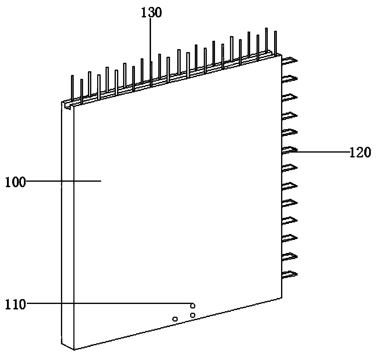
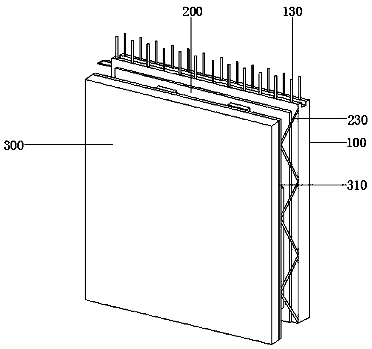
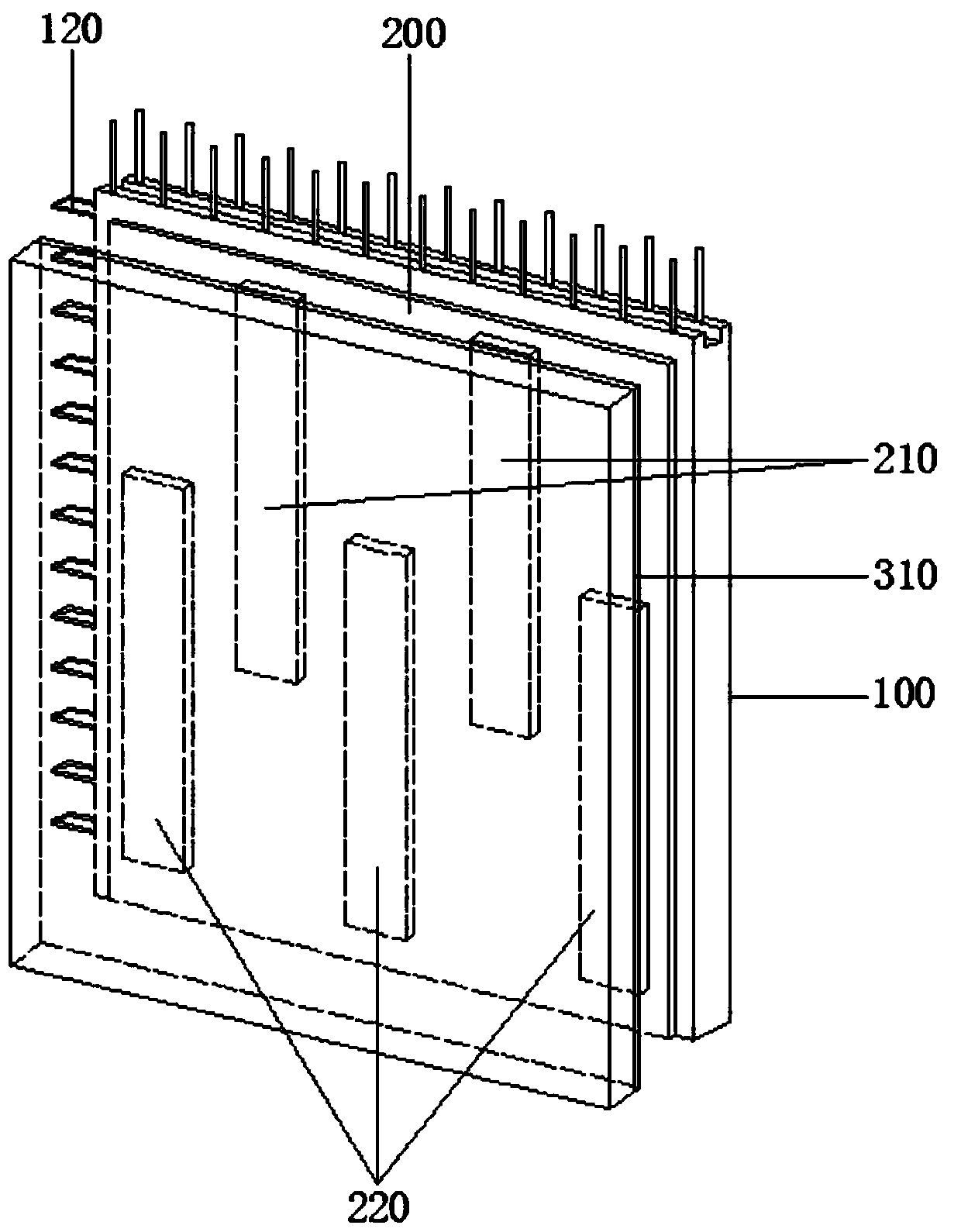
[0045] S3: Steel bar inspection: It is necessary to check whether the reserved positions of the side steel bars 120, embedded steel bars 130 and connecting steel bars 230 meet the standards, and the position deviation shall...


PUM


Abstract

The invention discloses a self-insulation composite shear wall structure in the technical field of building assemblies and a construction technology. The self-insulation composite shear wall structure comprises a main wall board, a hard sandwich insulation layer board and a deputy wall board, the front side wall of the main wall board is fixedly connected with the hard sandwich insulation layer board through a bolt, the front side wall of the hard sandwich insulation layer board is in contact with the deputy wall board, the rear side wall of the main wall board is fixedly connected with a demolding support plate through a bolt, and a reversed hole is formed in the rear side wall of the main wall board. According to the self-insulation composite shear wall structure and the construction technology, the hard sandwich insulation layer board additionally arranged can be used for fixing a top rib plate and a bottom rib plate, after cooperating with casting, the characteristics of insulation compression plates of the top rib plate and the bottom rib plate are used, the hard sandwich insulation layer board can be effectively matched with a soft sandwich insulation layer board, air is conveniently blocked, the self-insulation effect is achieved, the casting amount is lowered, on the basis of guaranteeing the intensity, the composite properties of the composite shear wall is increased, and the using range is increased.

Description

technical field [0001] The invention relates to the technical field of building components, in particular to a self-insulating laminated shear wall structure and construction technology. Background technique [0002] Shear walls are also called wind-resistant walls, seismic walls or structural walls. Walls in houses or structures that mainly bear horizontal loads and vertical loads (gravity) caused by wind loads or earthquakes to prevent structural shear (shear) damage. Also known as seismic walls, generally made of reinforced concrete. [0003] The laminated shear wall is a classification of the shear wall, which is formed by superimposing two concrete wall panels, and the superimposed method uses steel trusses to link the concrete panels on both sides together. After the prefabrication is completed , There is a cavity environment between the plates, and the pouring work in the cavity will be performed after the on-site installation is in place. [0004] When the existin...

Claims


Application Information

Patent Timeline
Patent Type & Authority Applications(China)
IPC IPC(8): E04B2/84E04B1/76
CPCE04B1/76E04B2/84
Inventor 李国钧谢雄美李圣迪
Owner 浙江舜元建筑产业化有限公司
Why Eureka
Try Eureka