Method and structure for eliminating mist on light energy heat collection device of solar water heater

A technology of solar water heaters and solar collector tubes, applied in the directions of solar thermal energy, solar collectors, and solar collector safety, can solve problems such as reducing the efficacy of solar water heaters absorbing solar energy, and achieve ingenious structure, convenient use, and improved utilization rate effect

Active Publication Date: 2019-09-20
徐锐
View PDF6 Cites 5 Cited by
  • Summary
  • Abstract
  • Description
  • Claims
  • Application Information

AI Technical Summary

Problems solved by technology

[0002] As people's awareness of energy conservation and environmental protection continues to increase, energy-saving and environmentally friendly products are gradually recognized and accepted by people, and solar water heaters are one of them; Touching the cold solar heat collecting tube in the lower morning will cast a layer of mist on the solar heat collecting tube, and the generation of mist will reduce the efficiency of solar water heaters in absorbing solar energy, and solar water heaters are generally installed on the roof of residential buildings. It is impossible to go to the roof every day to observe the state of solar heat collection and perform defogging operations

Method used


Image

  • Method and structure for eliminating mist on light energy heat collection device of solar water heater
  • Method and structure for eliminating mist on light energy heat collection device of solar water heater
  • Method and structure for eliminating mist on light energy heat collection device of solar water heater

Examples


Embodiment

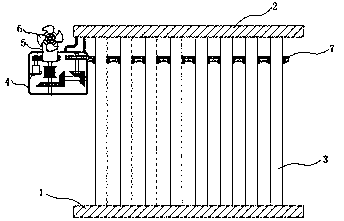
[0027] refer to Figure 1-3 , to eliminate the structure of the mist on the light energy heat collecting device of the solar water heater, including the upper mounting frame 2 and the lower fixing frame 1, and a plurality of solar heat collecting tubes 3 are jointly installed between the upper mounting frame 2 and the lower fixing frame 1, and a plurality of The solar collector tubes 3 are arranged at equal intervals, and deep groove ball bearings 24 are installed on the outer wall of each solar collector tube 3, and a transmission gear 7 and a fan 14 are installed on the outer ring of the deep groove ball bearings 24, and the adjacent two Mesh between two transmission gears 7;

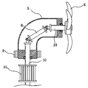
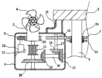
[0028] On the upper mounting frame 2, a transmission case 4 is installed through a connecting frame 12, a wind power generating mechanism is installed through the top wall of the transmission case 4, a generator 11 is fixedly installed on the inner wall of the transmission case 4, and the input end of...


PUM


Abstract

The invention discloses a structure for eliminating mist on a light energy heat collection device of a solar water heater. The structure comprises an upper installing frame and a lower installing frame, multiple solar heat collection pipes are jointly installed between the upper installing frame and the lower installing frame, the outer side wall of each solar heat collection pipe is provided with a deep groove ball bearing, and a transmission gear and a fan are installed on an outer ring of each deep groove ball bearing; and a transmission case is installed on the upper installing frame through a connecting frame, and a wind power generation mechanism is installed on the top wall of the transmission case in a penetrating manner. The invention further discloses a method for eliminating the mist on the light energy heat collection device of the solar water heater. The method comprises the following steps of 1 installing, 2 direction adjusting and 3 mist removing. According to the structure and the method for eliminating the mist on the light energy heat collection device of the solar water heater, the structure is skillful, use is convenient, wind energy is converted into electric energy to provide power for the device, the mist on the solar heat collection pipes can be effectively removed, and energy conservation and environment protection are achieved; and meanwhile, the direction of a wind wheel can be adjusted in time according to different using environment and different time, and then the wind energy utilization rate is increased.

Description

technical field [0001] The invention relates to the technical field of solar water heaters, in particular to a method and structure for eliminating fog on a light energy heat collecting device of a solar water heater. Background technique [0002] As people's awareness of energy conservation and environmental protection continues to increase, energy-saving and environmentally friendly products are gradually recognized and accepted by people, and solar water heaters are one of them; Touching the cold solar heat collecting tube in the lower morning will cast a layer of mist on the solar heat collecting tube, and the generation of mist will reduce the efficiency of solar water heaters in absorbing solar energy, and solar water heaters are generally installed on the roof of residential buildings. It is impossible to go to the roof every day to observe the state of solar heat collection and perform defogging operations. [0003] For this reason, we propose to eliminate the metho...

Claims


Application Information

Patent Timeline
Patent Type & Authority Applications(China)
IPC IPC(8): F24S40/00F04D25/16F04D25/08F04D25/02F03D15/00F03D9/11F03D7/02
CPCF03D7/0204F04D25/02F04D25/08F04D25/163F04D25/166F05B2270/321F05B2270/602F03D9/11F03D15/00F24S40/00Y02E10/40Y02E10/72Y02E70/30
Inventor 钱贤鑫
Owner 徐锐
Why Eureka
Try Eureka