Robot vision measurement system based on external tracking and calibration method thereof

A technology of robot vision and measurement system, which is applied in the direction of measuring devices, instruments, and optical devices, etc. It can solve the problems of time-consuming and labor-intensive marking point layout and cleaning, low data acquisition efficiency, and small data acquisition volume, so as to avoid the problem of solving results The effects of different, stable solution results, and good measurement accuracy

Active Publication Date: 2019-09-20
HUAZHONG UNIV OF SCI & TECH
View PDF7 Cites 15 Cited by
  • Summary
  • Abstract
  • Description
  • Claims
  • Application Information

AI Technical Summary

Problems solved by technology

Contact measurement generally has high precision, but it belongs to point measurement, the data acquisition efficiency is low, and the amount of data acquisition is small
After arranging marker points, the photogrammetry system can realize batch acquisition of measuring points, and the efficiency and quantity of data acquisition have been improved to a certain extent, but most of them can only be used for the measurement of key dimension

Method used


Image

  • Robot vision measurement system based on external tracking and calibration method thereof
  • Robot vision measurement system based on external tracking and calibration method thereof
  • Robot vision measurement system based on external tracking and calibration method thereof

Examples


Embodiment Construction

[0039]In order to make the object, technical solution and advantages of the present invention clearer, the present invention will be further described in detail below in conjunction with the accompanying drawings and embodiments. It should be understood that the specific embodiments described here are only used to explain the present invention, not to limit the present invention. In addition, the technical features involved in the various embodiments of the present invention described below can be combined with each other as long as they do not constitute a conflict with each other.

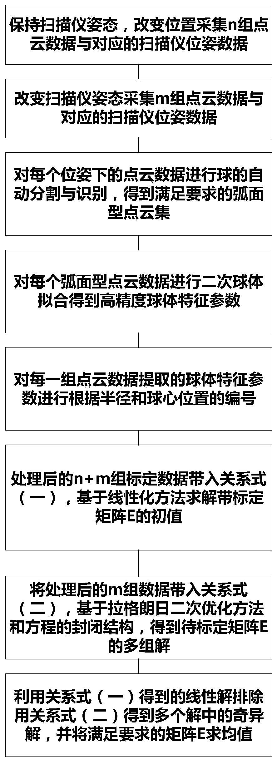
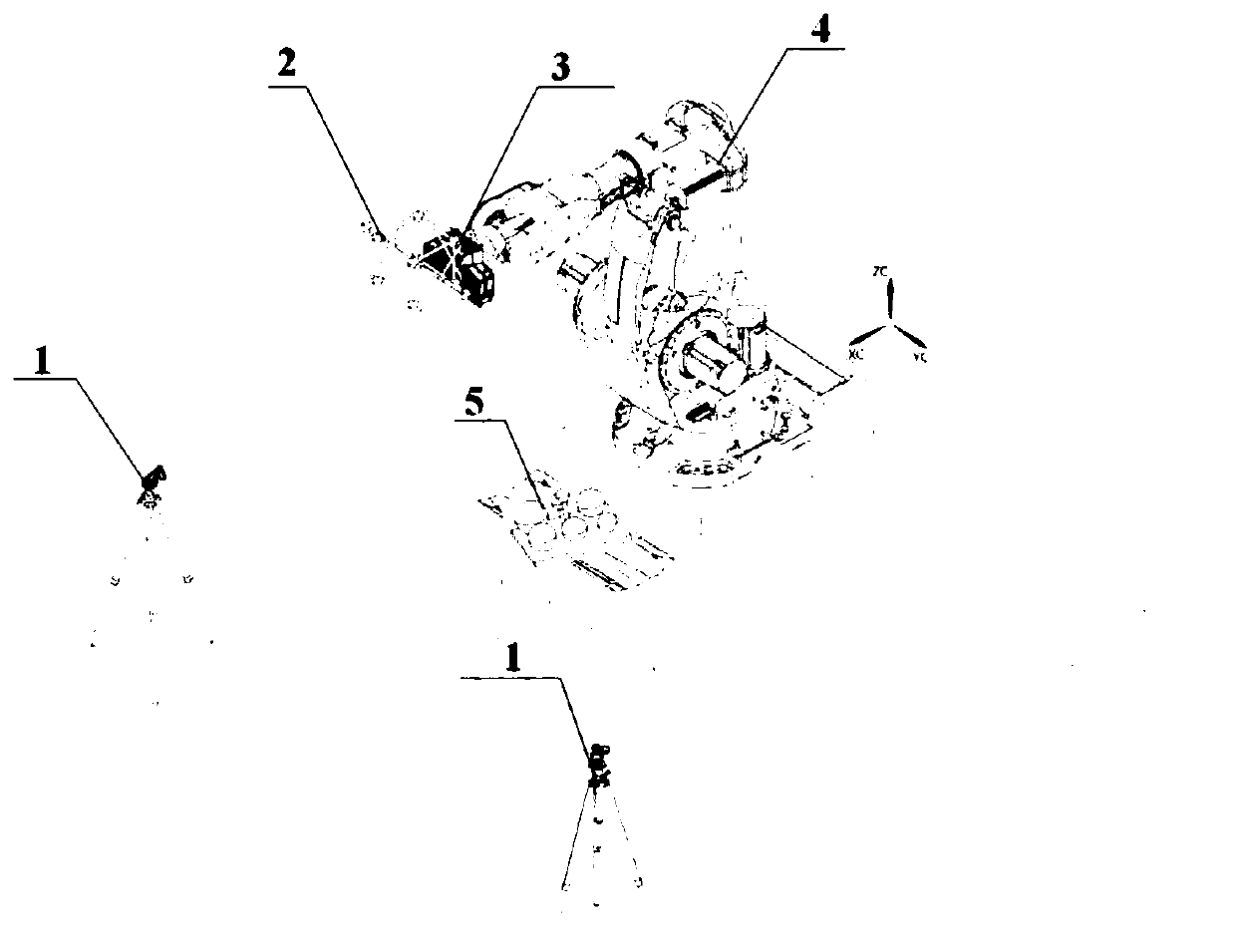
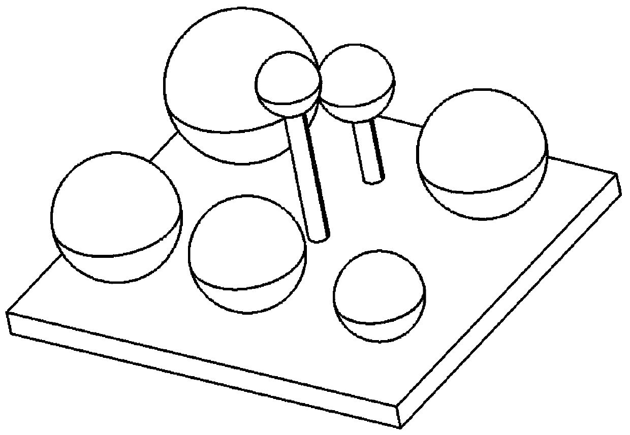
[0040] Such as figure 2 As shown, a robot vision measurement system based on external tracking is characterized in that the vision measurement system includes an external tracking device 1, a three-dimensional spherical cage target 2, an area scanner 3, an industrial robot 4 and a calibration device 5, wherein:

[0041] The area scanner 3 is arranged at the end of the industrial robot, the thre...


PUM


Abstract

The invention belongs to the field of robot vision measurement, and discloses a robot vision measurement system based on external tracking and a calibration method thereof. The robot vision measurement system comprises an external tracking device, a stereoscopic ball cage target, an area array scanner, an industrial robot and a calibration device, wherein the area array scanner is arranged at the tail end of the industrial robot, and the stereoscopic ball cage target is arranged on the area array scanner. The invention further discloses a calibration method of the robot vision measurement system. The calibration method comprises the steps of: scanning the stereoscopic ball cage target by adopting the external tracking device, and scanning the calibration device by adopting the area array scanner; acquiring two sets of target data in a state of constant attitude and variable position and in a state of variable attitude and position; establishing a conversion relationship between mutual coordinate systems; and finally, calculating to obtain a conversion matrix between an area array scanner coordinate system and a stereoscopic ball cage target coordinate system by utilizing the two sets of data. The robot vision measurement system avoids the different solution results which are possibly caused by processing the same data by different people or at different moments, and realizes the stability and consistency of calibration and solution.

Description

technical field [0001] The invention belongs to the field of robot vision measurement, and more specifically relates to a robot vision measurement system based on external tracking and a calibration method thereof. Background technique [0002] The measurement of large parts is widely used in many aspects such as digital measurement, digital processing, and digital assembly in the field of industrial manufacturing. It is one of the technical directions to realize the automation and intelligence of industrial manufacturing. [0003] The measurement of existing large parts is divided into contact type and non-contact type. Contact measurement includes three-coordinate measuring machine and binocular three-coordinate measurement system; non-contact measurement mainly includes photogrammetry, area scanner or line laser scanner measurement scheme based on marker point splicing. Contact measurement generally has high precision, but it belongs to point measurement, the data acquis...

Claims


Application Information

Patent Timeline
IPC IPC(8): G01B11/00
CPCG01B11/002
Inventor 李文龙彭泽龙蒋诚王刚
Owner HUAZHONG UNIV OF SCI & TECH
Why Eureka
Try Eureka