
Heliostat calibration system and method

A heliostat and a technology to be calibrated, which is applied in the field of solar power generation, and can solve the problems of complex processing methods, affecting the calibration efficiency of heliostats, and long consumption time.

Active Publication Date: 2019-09-20
深圳中科能投能源有限公司
View PDF10 Cites 6 Cited by
  • Summary
  • Abstract
  • Description
  • Claims
  • Application Information

AI Technical Summary

Problems solved by technology

This method is complex and takes a long time. When the heliostat field contains thousands of heliostats, it greatly affects the calibration efficiency of the heliostat.

Method used


Image

  • Heliostat calibration system and method
  • Heliostat calibration system and method
  • Heliostat calibration system and method

Examples


Embodiment 1

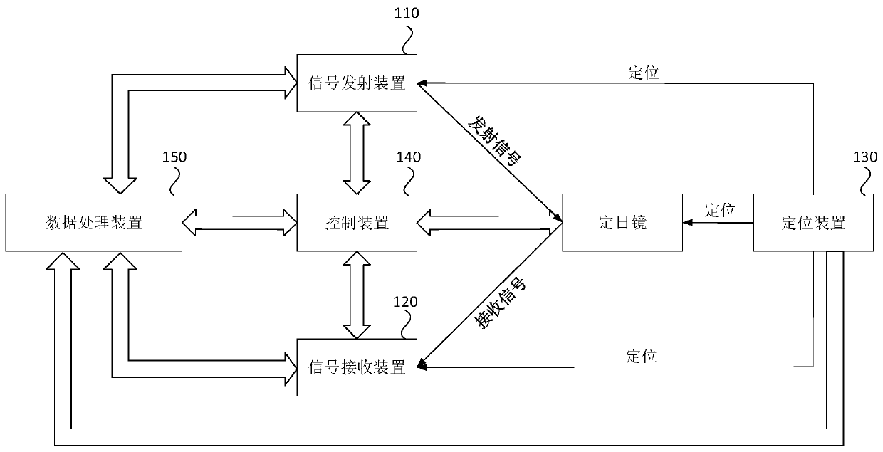
[0048] figure 1 It is a structural block diagram of the heliostat calibration system provided in Embodiment 1 of the present application. This embodiment can be adapted to the situation of calibrating each heliostat in the heliostat field. The system can be composed of software and / or hardware It can be realized in a manner, and the method for calibrating the heliostat provided in this application can be executed.

[0049] like figure 1 As shown, the calibration system of the heliostat includes: at least one signal transmitting device 110, at least one signal receiving device 120, a positioning device 130, a control device 140 and a data processing device 150; wherein:

[0050] The positioning device 130 is configured to determine the spatial positions of the at least one signal transmitting device 110, the at least one signal receiving device 120, and the heliostat to be calibrated, and the at least one signal transmitting device 110, the at least one signal receiving device...

Embodiment 2

[0084] Figure 9 It is a flow chart of the calibration method of the heliostat provided in Embodiment 2 of the present application. The method provided in this embodiment may be implemented by the calibration system of the heliostat described above.

[0085] like Figure 9 As shown, the calibration system and method of the heliostat include:

[0086] S910. Determine the spatial positions of the at least one signal transmitting device, at least one signal receiving device, and the heliostat to be calibrated by the positioning device, and set the at least one signal transmitting device, at least one signal receiving device, and the positioning device to be calibrated The spatial position of the heliostat is uploaded to the data processing device.

[0087] S920. Send a control signal to the at least one signal transmitting device and at least one signal receiving device by the control device, so as to control the signal transmitting device and the signal receiving device to tr...


PUM


Abstract

The embodiment of the invention discloses a heliostat calibration system and method. According to the technical scheme, the positions of a signal transmitting device, a signal receiving device and a heliostat to be calibrated are positioned, the theoretical transmitting angle and the theoretical receiving angle of at least one of an optical signal, an image signal and a radio signal are determined, a simultaneous equation is constructed according to the spatial positions of the at least one signal transmitting device, the at least one signal receiving device and the heliostat to be calibrated and according to the transmitting direction, the receiving direction and the angle of at least one of the optical signal, the image signal and the radio signal, so that the deviation parameter of the heliostat to be calibrated is determined, and the heliostat to be calibrated is calibrated according to the deviation parameter. By adopting the technical scheme provided by the invention, the aim of improving the calibration efficiency of the heliostat can be achieved.

Description

technical field [0001] The embodiments of the present application relate to the technical field of solar power generation, and in particular to a calibration system and method for a heliostat. Background technique [0002] With the rapid development of economy and society, direct or indirect environmental problems such as smog and global warming are increasing, and people are paying more and more attention to environmental protection. Therefore, human society pays more and more attention to new energy sources, especially the utilization of solar energy. [0003] In central tower collector power plants, the collector on top of the collector tower receives sunlight reflected from a field of heliostats. The collector converts the energy into high-pressure, high-temperature steam output, which can then be sent to a turbine for electricity generation. Heliostats are generally installed on the ground around the tower. Each heliostat has a rigid reflective surface to track the s...

Claims


Application Information

Patent Timeline
IPC IPC(8): G05D3/12F24S50/20
CPCG05D3/12F24S50/20F24S2050/25Y02E10/47
Inventor 孙海翔夏越赵晓东滕广平肖强陈中柱莫小宇段谦君蔡正斌杜琪曾国平余春林张操操黄长陶沙余伟
Owner 深圳中科能投能源有限公司
Learn More