Wire-wound resistor resistance wire winding equipment and winding method thereof

A wire-wound resistor and equipment technology, applied in the field of winding equipment, can solve the problems of large friction loss, low degree of automation, time-consuming and labor-intensive use, etc., and achieve the effect of reducing floor space, high degree of automation, and time-saving and labor-saving use.

Pending Publication Date: 2019-09-20
BENGBU ZHENGYUAN ELECTRONICS TECH
View PDF0 Cites 0 Cited by
  • Summary
  • Abstract
  • Description
  • Claims
  • Application Information

AI Technical Summary

Problems solved by technology

[0004] The purpose of the present invention is to solve the problem that the existing wire-wound resistor wire-wound winding equipment has a low degree of automation for the wire-wound winding work, is time-consuming and labor-intensive to use, and is inconvenient to operate; The insulating frame is used to wind the resistance wire, the efficiency of the equipment is low, and the overall floor space is large; the winding equipment winds the resistance wire on the insulating frame is not uniform and comprehensive, and the quality of the equipment winding resistance wire is poor ; and the winding equipment cannot be installed with insulating frames of different lengths and diameters to wind the resistance wires, and the adaptability is poor; the winding equipment mov

Method used


Image

  • Wire-wound resistor resistance wire winding equipment and winding method thereof
  • Wire-wound resistor resistance wire winding equipment and winding method thereof
  • Wire-wound resistor resistance wire winding equipment and winding method thereof

Examples


Embodiment Construction

[0048] The technical solutions of the present invention will be clearly and completely described below in conjunction with the embodiments. Apparently, the described embodiments are only some of the embodiments of the present invention, not all of them. Based on the embodiments of the present invention, all other embodiments obtained by persons of ordinary skill in the art without creative efforts fall within the protection scope of the present invention.

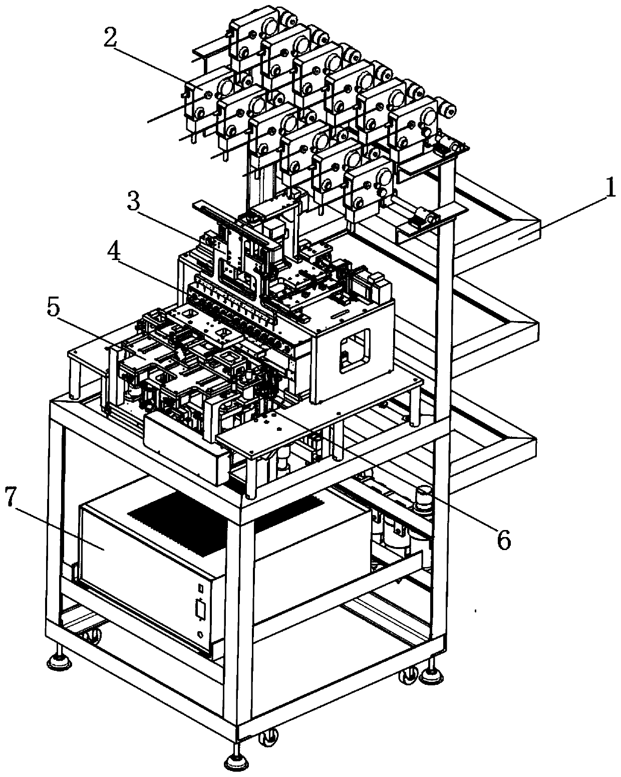
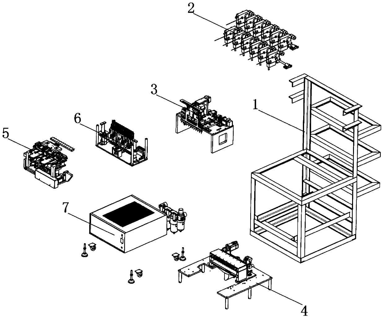
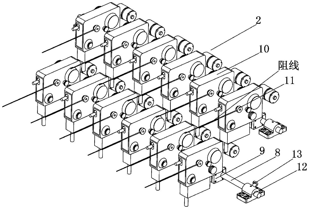
[0049] see Figure 1-13 As shown in the figure, a wire-wound resistor resistance winding device includes an installation table 1, a wire material tray 2, a lead base 3, a front hanging tray 4, a rear hanging tray 5, a crimping table 6 and a power distribution seat 7. A wire tray 2 is arranged on the top of the table 1, and a lead base 3 is arranged under the wire tray 2, and a front hanging tray 4 is arranged under the lead tray 3, and a rear hanging tray 5 is arranged on one side of the front hanging tray 4, and the rear h...


PUM


Abstract

The invention discloses wire-wound resistor resistance wire winding equipment and a winding method thereof. The wire-wound resistor resistance wire winding equipment comprises a mounting table, wire trays, a lead wire base, a front hanging disc, a back hanging disc, a wire pressing bench and a power distribution base. The top portion of the mounting table is provided with the wire trays; the lead wire base is arranged under the wire trays; and the front hanging disc is arranged under the lead wire base. The beneficial effects are that the equipment is high in working automation degree, and saves time and labor; one-to-one coordinated resistance wire winding work is realized through multiple wire trays, multiple lead cones and multiple insulation skeletons, thereby greatly improving work efficiency of the equipment and reducing land occupation area of the equipment; a hydraulic pump drives stretching bars to move back and forth cooperated with back plug cones so as to drive the insulation skeletons to move back and forth to wind resistance wires, thereby ensuring that the resistance wires are wound on the insulation skeletons more uniformly and comprehensively, and improving resistance wire winding efficiency and winding quality of the equipment.

Description

technical field [0001] The invention relates to a winding device, in particular to a wire-wound resistor resistance wire winding device and a winding method thereof, and belongs to the technical field of wire-wound resistor resistance wire winding device application. Background technique [0002] Wire-wound resistors are a kind of resistors made of different types of resistance wires wound on an insulating frame, with protective paint or glass glaze on the surface. Advantages: low noise, no current noise and non-linearity. Winding equipment is indispensable for the processing and assembly of wirewound resistors. The main function of winding equipment is to thread and connect the resistance wires, and wind the resistance wires on the insulating skeleton to complete the processing of wire wound resistors and resistance wires. Assembly, to ensure the normal use of wirewound resistors in the later stage. [0003] The existing wire-wound resistor resistance wire winding equipme...

Claims


Application Information

Patent Timeline
IPC IPC(8): H01C17/04
CPCH01C17/04
Inventor 夏云
Owner BENGBU ZHENGYUAN ELECTRONICS TECH
Why Eureka
Try Eureka