
Manufacturing technology of laser detection jig plate

A laser detection and manufacturing process technology, applied in the field of laser detection fixture plate manufacturing process, can solve problems such as increased cost, insufficient temperature control, and unfavorable long-term development, and achieves the effect of preventing deformation, saving manpower and material resources, and reducing costs.

Active Publication Date: 2019-09-24
DONGGUAN SHENGXIANG PRECISION METAL
View PDF6 Cites 3 Cited by
  • Summary
  • Abstract
  • Description
  • Claims
  • Application Information

AI Technical Summary

Problems solved by technology

[0002] In the inspection process of the production and processing process of some specific products, lasers are often used for inspections, and due to the high accuracy requirements and high energy of the lasers, it is generally necessary to use special fixture plates to fix and fix the products. detection, and the manufacturing process of this type of fixture board is not easy
Most of the existing fixture plates for laser detection are limited by the technological level, and there are deficiencies in the production process. For example, the most common problem is that the vacuum heat treatment temperature Insufficient control leads to the easy deformation of the fixture board, which cannot meet the standards that can be applied to the inspection process, wastes manpower and material resources, increases the cost of production and manufacturing, and is not conducive to the needs of long-term development

Method used


Image

  • Manufacturing technology of laser detection jig plate
  • Manufacturing technology of laser detection jig plate
  • Manufacturing technology of laser detection jig plate

Examples


Embodiment Construction

[0026] The present invention will be described in further detail below in conjunction with the accompanying drawings.

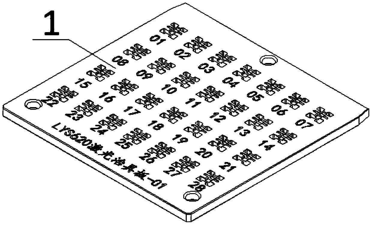
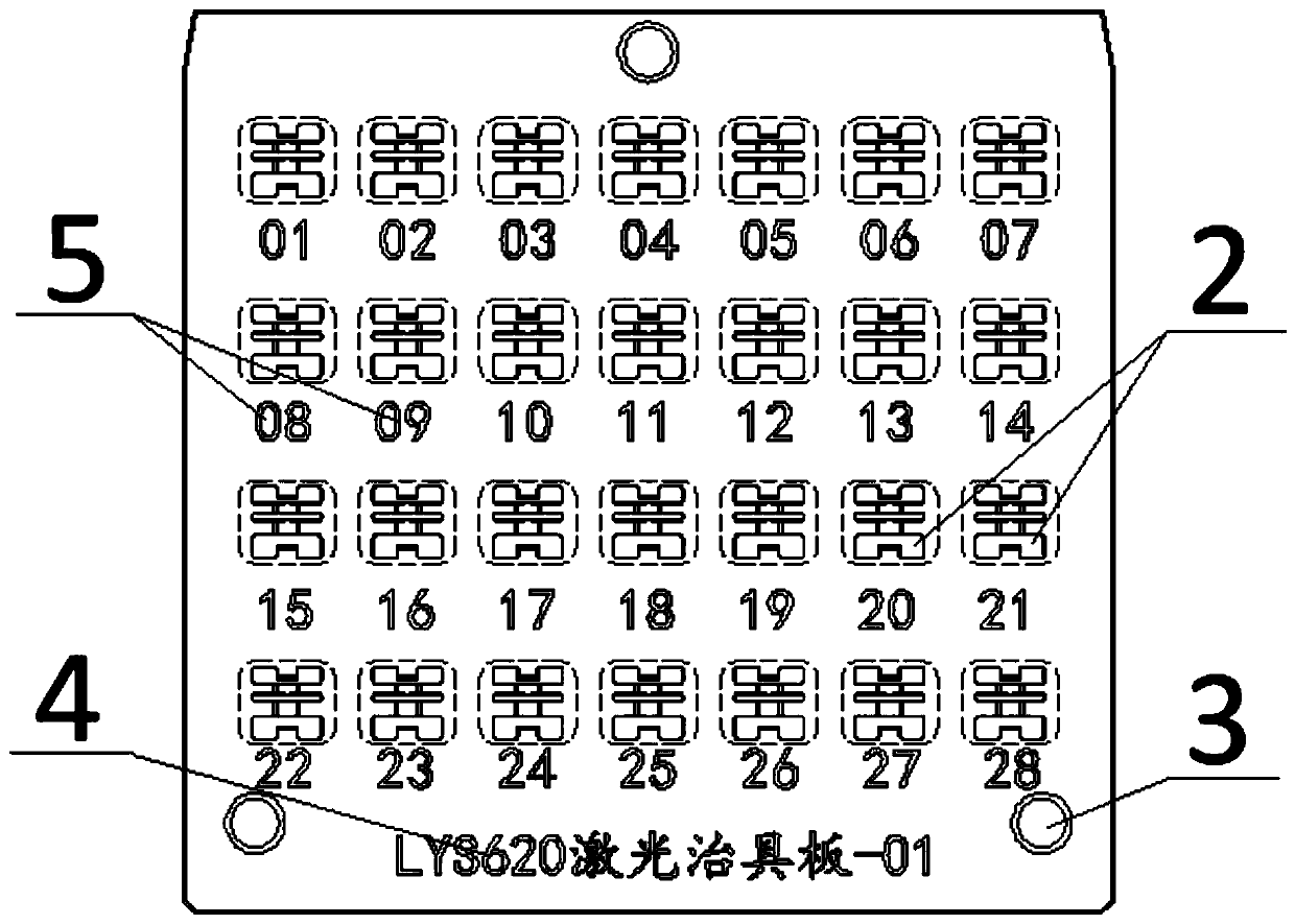
[0027] figure 1 Schematically shows the structure of the laser detection fixture plate manufactured according to an embodiment of the present invention, figure 2 shown figure 1 The front structure of the laser detection fixture board in ; image 3 shows up shows up figure 1 The side structure of the laser inspection fixture plate in . Such as Figure 1-3 As shown, the jig plate 1 is roughly square, and a plurality of installation stations 2 arranged in a row are distributed on it. The installation stations 2 are used to install the workpiece products to be detected by laser, and the number and distribution can be set according to needs. It is preferably 28 in 4 rows and 7 columns.

[0028] Several through holes 3 are also provided at the edge of the jig plate 1 , and the through holes 3 are used for fixing and installing the jig plate 1 . Wherein, the...


PUM

PropertyMeasurementUnit
Lengthaaaaaaaaaa
Widthaaaaaaaaaa
Thicknessaaaaaaaaaa

Abstract

The invention relates to the field of detection tool manufacturing, and discloses a manufacturing technology of a laser detection jig plate. The technology comprises the following steps that (1) a blank of the jig plate is ground on a grinding machine to be square, and the sides of the blank are machined to form right angles; (2) the jig plate is subjected to CNC rough machining, and multiple mounting stations are formed on the jig plate; (3) the jig plate is subjected to vacuum heat treatment; (4) the jig plate is subjected to fine grinding on the grinding machine; (5) the jig plate is subjected to slow wire feed machining, and multiple through holes are formed in the jig plate; (6) the jig plate is subjected to CNC finish machining in place; and (7) the surface of the jig plate is subjected to carburizing treatment. According to the manufacturing technology of the laser detection jig plate, through upgrading and modification to the original technology, the grinding temperature and the cutting heating temperature are controlled more effectively, the phenomenon of deformation is avoided in the manufacturing process, and therefore manpower and material resources are saved, the cost of production and manufacturing is reduced, and the requirement for long-term development can be met easily.

Description

technical field [0001] The invention relates to the field of detection tool manufacturing, in particular to a manufacturing process of a laser detection jig plate. Background technique [0002] In the inspection process of the production and processing process of some specific products, lasers are often used for inspections, and due to the high accuracy requirements and high energy of the lasers, it is generally necessary to use special fixture plates to fix and fix the products. Inspection, and the manufacturing process of this type of fixture board is not easy. Most of the existing fixture plates for laser detection are limited by the technological level, and there are deficiencies in the production process. For example, the most common problem is that the vacuum heat treatment temperature Insufficient control leads to the easy deformation of the jig plate, which cannot meet the standards that can be applied to the testing process, wastes manpower and material resources, ...

Claims


Application Information

Patent Timeline
IPC IPC(8): B23P15/00
CPCB23P15/00
Inventor 邹检发
Owner DONGGUAN SHENGXIANG PRECISION METAL
Learn More