
Multi-stage spiral water removal machine used in garbage classifying resource recycling device

A technology of resource regeneration and garbage classification, applied in the direction of presses, filtration separation, separation methods, etc., can solve the problems of low dehydration rate, uneven dryness of materials, simple structure, etc., and achieve improved dehydration efficiency and dehydration adequacy Effect

Pending Publication Date: 2019-09-24
河南中成环保科技股份有限公司
View PDF1 Cites 2 Cited by
  • Summary
  • Abstract
  • Description
  • Claims
  • Application Information

AI Technical Summary

Problems solved by technology

But the existing screw dehydrator has simple structure, insufficient dehydration, and low dehydration rate. For this reason, the Chinese patent authorization publication number is CN206264414U, and the utility model patent with the patent application number of 201621374212.7 discloses a kind of garbage with multi-stage spiral dehydration device. Treatment equipment, which uses the change of the pitch of the helical blade and the change of the screw to gradually compress the extrusion space to form a multi-stage dehydration mechanism. Although the dehydration rate and dehydration effect have been improved to a certain extent, the garbage disposal equipment of this multi-stage spiral dehydration device The dehydration method has not changed, and the kitchen waste cannot be filtered, and the peel and liquid pasta waste cannot be separated and dehydrated in different ways. It still has a low dehydration rate and is affected by the speed of the spiral rotation and the content of the material. Influenced by the amount of water, the dryness of the dehydrated material is uneven

Method used


Image

  • Multi-stage spiral water removal machine used in garbage classifying resource recycling device
  • Multi-stage spiral water removal machine used in garbage classifying resource recycling device
  • Multi-stage spiral water removal machine used in garbage classifying resource recycling device

Examples


Embodiment Construction

[0021] In the description of the present invention, it should also be noted that, unless otherwise clearly specified and limited, the terms "installation", "installation", "connection" and "connection" should be understood in a broad sense, for example, it may be a fixed connection, It can also be a detachable connection or an integral connection; it can be a mechanical connection or an electrical connection; it can be a direct connection or an indirect connection through an intermediary, and it can be the internal communication of two components. Those of ordinary skill in the art can understand the specific meanings of the above terms in the present invention in specific situations.

[0022] The following will clearly and completely describe the technical solutions in the embodiments of the present invention with reference to the accompanying drawings in the embodiments of the present invention. Obviously, the described embodiments are only some, not all, embodiments of the p...


PUM


Abstract

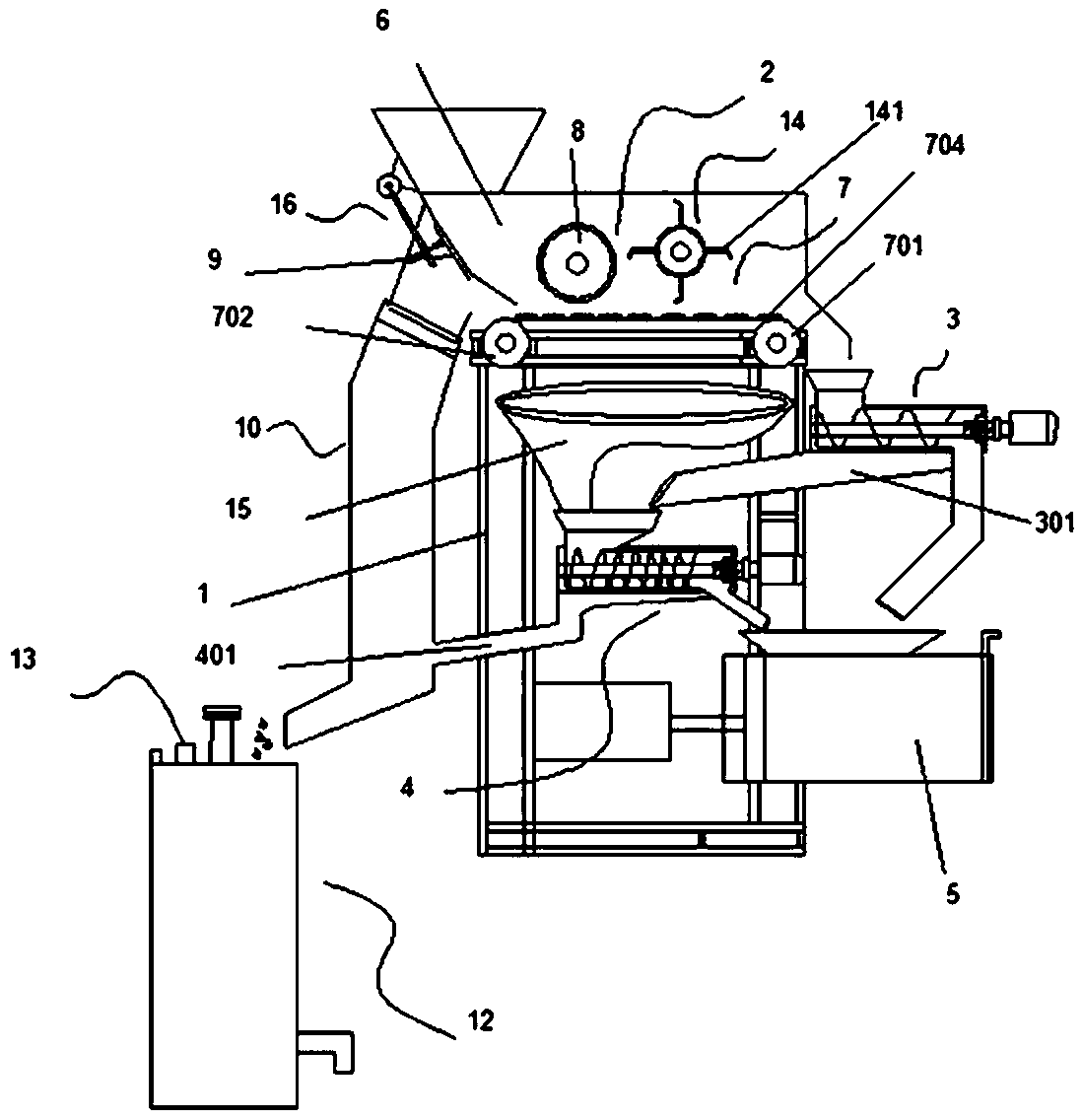
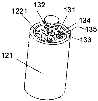
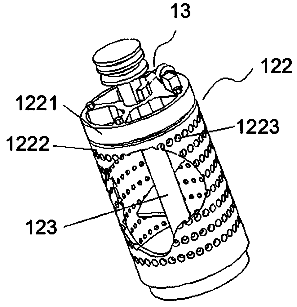
The invention discloses a multi-stage spiral water removal machine used in a garbage classifying resource recycling device. The machine comprises a rack, a supply device, a first-stage water removal device, a second-stage water removal device and a cake pressing machine. The supply device is arranged on the upper end of the rack and comprises a material inlet box, a half type filter conveying belt assembly arranged in the material inlet box and a pressing roller used for pressing water removal. The pressing roller is arranged above the half type filter conveying belt assembly, a water filter opening is formed in an inlet of the material inlet box in an inclined manner, a filter net and a sewage pipeline I are arranged on the water filter opening, and the first-stage water removal device and the second-stage water removal device are used for treating garbage separated out of the upper and the lower of the half type filter conveying belt assembly. Peels and fluid cooked wheaten food garbage are separated to be subjected to independent water removal, the mutual influences or obstruction is removed, and the water removal efficiency and water removal sufficiency are improved.

Description

technical field [0001] The invention relates to the technical field of material dehydration and filtration, in particular to a multi-stage spiral dehydrator used in waste sorting resource regeneration equipment. Background technique [0002] The dehydrator is one of the indispensable equipment in the organic waste treatment system such as kitchen organic waste and garden organic waste. This kind of dehydrator is mainly a spiral dehydrator. The specific working process is that the material is pushed along the shaft by the spiral rotating blade Forward, during the forward process, the material is affected by the changing screw pitch to form an extrusion force, so that the material is mechanically dehydrated under pressure, and the water can only be discharged at the outlet through the screen, and the dehydrated material is discharged at the outlet. . But the existing screw dehydrator has simple structure, insufficient dehydration, and low dehydration rate. For this reason, th...

Claims


Application Information

Patent Timeline
Patent Type & Authority Applications(China)
IPC IPC(8): B30B9/20B30B9/12B30B9/26B01D33/067B01D33/11B01D33/80
CPCB01D33/067B01D33/11B01D33/806B30B9/12B30B9/121B30B9/20B30B9/26
Inventor 王杨许静王少安杨飞
Owner 河南中成环保科技股份有限公司
Learn More