Multilayer headbox structure for a fiber web machine and method for forming a fiber web

A technology of fiber web machine and fiber web, which is applied in the direction of paper machine, paper machine wet end, textile and paper making, etc. It can solve the problems of liquid layer mixing and fiber web quality reduction, and achieve the effect of cost reduction

Active Publication Date: 2019-09-24
VALMET TECH OY
View PDF5 Cites 0 Cited by
  • Summary
  • Abstract
  • Description
  • Claims
  • Application Information

AI Technical Summary

Problems solved by technology

[0005] However, there remains the problem that, due to turbulence in the individual liquid layers, mixing of the liquid layers takes place to a large extent once they pass through the blades
Therefore, undesired interactions and chemical reactions may occur between the additives, so that a reduction in the quality of the fiber web to be formed must be expected

Method used


Image

  • Multilayer headbox structure for a fiber web machine and method for forming a fiber web
  • Multilayer headbox structure for a fiber web machine and method for forming a fiber web

Examples


Embodiment Construction

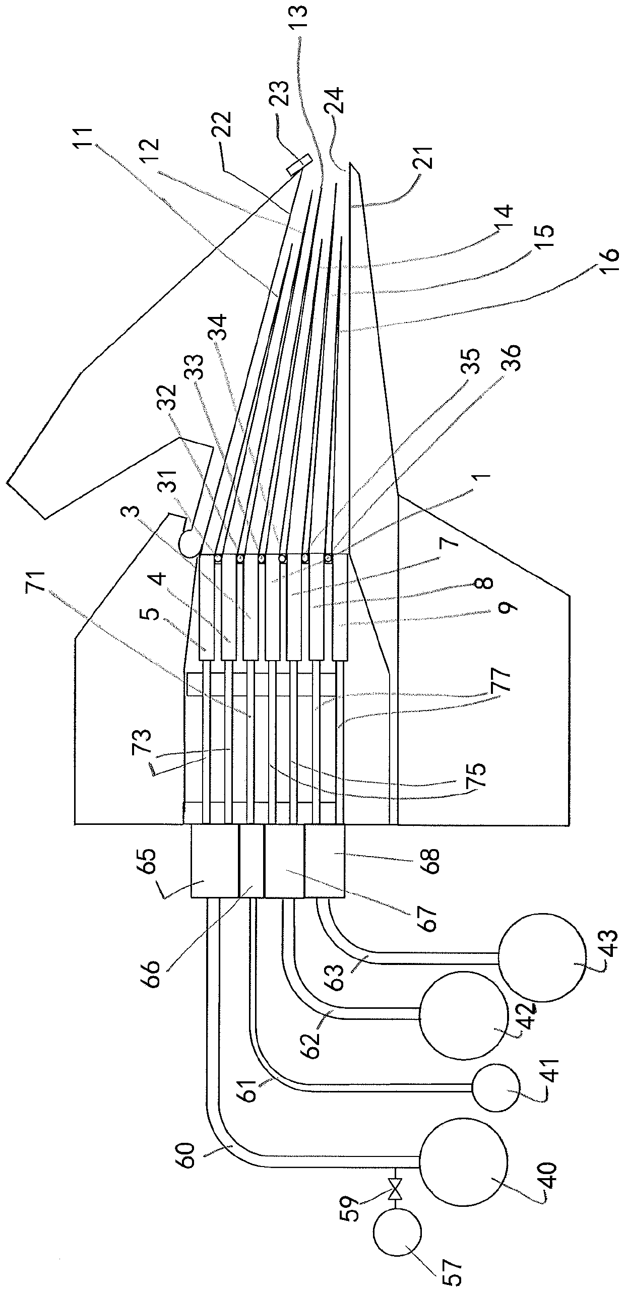
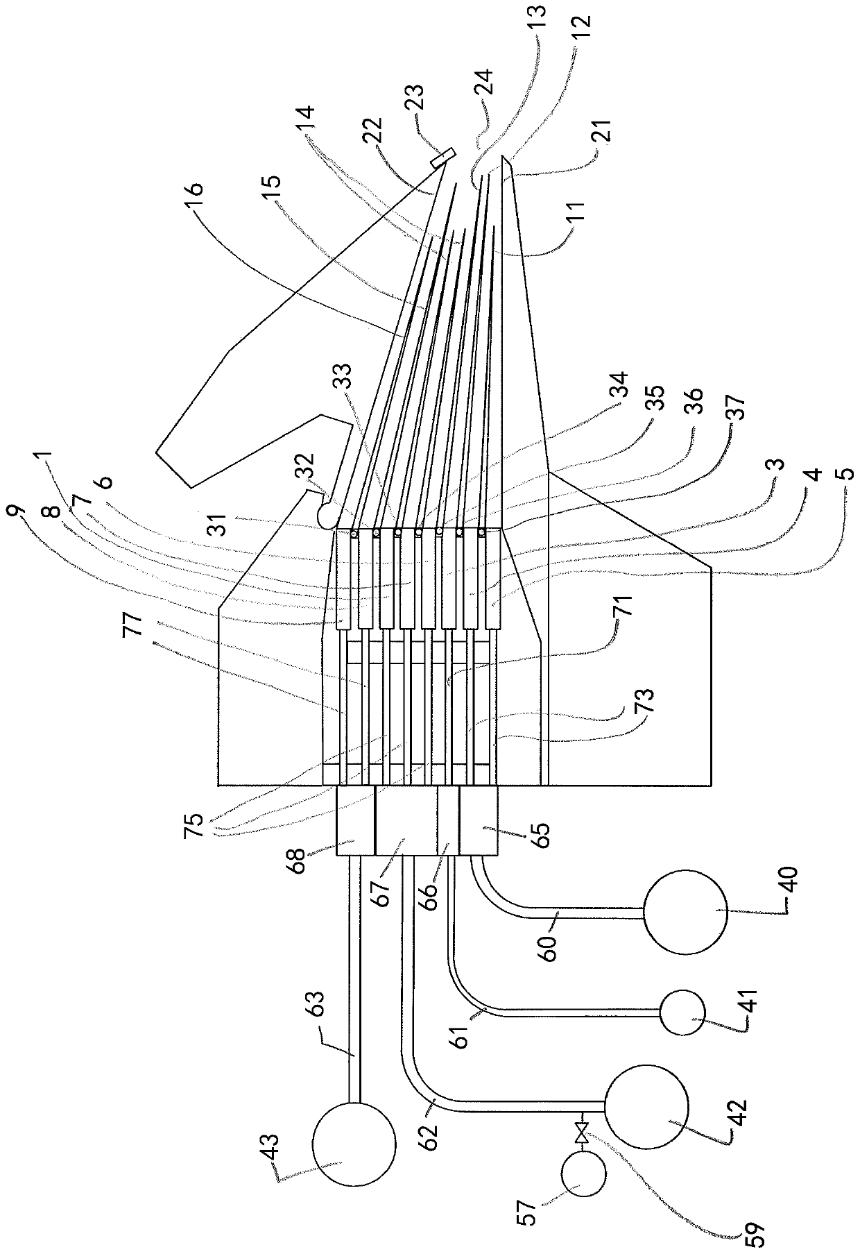
[0035] figure 1 is a cross-sectional view of a multilayer headbox structure according to the invention for a fibrous web machine, such as a paper or board machine, for forming a fibrous web.

[0036] exist figure 1 , from left to right, the headbox comprises stock headers 40, 41, 42, 43, which are arranged at the bottom on the left side in said figure. Liquids such as pulp suspension and water are supplied from the stock feed mains 40, 41 , 42, 43 via manifolds 60, 61 , 62, 63 serving as supply means into the intermediate chambers 65, 66, 67, 68 respectively.

[0037] Optionally intermediate chambers 65, 66, 67, 68 are provided as balancing chambers. That is, the stock feed manifolds 40, 41, 42, 43 may be directly or integrally connected to the headbox.

[0038] Furthermore, a diffuser chamber is provided, in which diffuser pipes 1, 3, 4, 5, 7, 8, 9 are arranged as diffusers, and a nozzle chamber with converging walls forming a weir opening (nozzle outlet) 24 21, 22. Each...


PUM


Abstract

The present invention relates to a multilayer headbox structure for a fiber web machine for forming a fiber web, comprising a multilayer headbox having a turbulence generator and a nozzle chamber having two converging walls forming a nozzle outlet. The turbulence generator has a plurality of diffusers creating turbulence in liquids supplied into each respective diffuser via feeding means for feeding the liquids, each of the diffusers having an outlet into the nozzle chamber, wherein central diffusers of the plurality of diffusers comprise a first central diffuser (3) and a second central diffuser (1, 7), the first central diffuser is connected with feeding means (66) feeding fresh water, dilution water, and/or white water into the first central diffuser, the first central diffuser has two blades (12, 13) arranged at its outlet and extending into the nozzle chamber in a converging manner, the blades separating the fresh water, dilution water, and/or white water as the liquid flowing through the first central diffuser from the liquids flowing through adjacent diffusers, the second central diffuser is connected with feeding means (67) feeding pulp suspension into the second central diffuser, the second central diffuser has an additional blade (14) arranged at the outlet, and the additional blade has a shorter length than the adjacent blade of the first central diffuser, and the central diffusers are arranged between a top ply diffuser (4, 5) and a back ply diffuser (8, 9), in which top ply diffuser top ply pulp suspension as the liquid flows through the top ply diffuser for forming a top ply of the fiber web and in which back ply diffuser back ply pulp suspension as the liquid flows through the back ply diffuser for forming a back ply of the fiber web.

Description

technical field [0001] The invention relates to a multilayer headbox structure for a fiber web machine, such as a paper or board machine, for forming a fiber web, and to a A method of forming a fibrous web in the forming section of a machine. Background technique [0002] At the start of the wet end of a paper or board machine, the headbox structure is basically used to supply mainly liquid substances, such as water and / or pulp suspension, onto the wires of the forming section. Additives such as refined fibers, fillers, cationic polymers such as cationic starch, etc. may be added to the water and / or pulp suspension. These liquid substances are supplied to the headbox through a water supply system or water supply system. In the forming section, the substance applied to the forming wire is then dewatered to form a fibrous web, such as a paper or board web. The fibrous web is then further transferred to a press section for additional dewatering and a dryer section in which t...

Claims


Application Information

Patent Timeline
Patent Type & Authority Applications(China)
IPC IPC(8): D21F1/02D21F11/04
CPCD21F1/02D21F11/04D21F1/026D21F1/028
Inventor 萨米·安蒂莱宁汉努·图尔佩宁
Owner VALMET TECH OY
Why Eureka
Try Eureka