Ball mounting equipment for ball ceramic bearing

A ceramic bearing, ball-type technology, applied in the direction of bearing components, shafts and bearings, mechanical equipment, etc., can solve the problems of low ball installation efficiency, reduced friction coefficient, low impact resistance, etc., to achieve sensitive response, high degree of automation, Precise positioning effect

Active Publication Date: 2019-09-24
浙江国信房地产营销策划有限公司
View PDF9 Cites 6 Cited by
  • Summary
  • Abstract
  • Description
  • Claims
  • Application Information

AI Technical Summary

Problems solved by technology

[0002] As we all know, bearings, as an important mechanical basic part, are often used to support mechanical rotating bodies, reduce the friction coefficient during its movement and ensure its rotation accuracy. Among bearings, ceramic bearings have excellent performance that metal bearings cannot match and are widely used. Applications, such as: not afraid of corrosion, low density, light weight, high elastic modulus, etc.; but the ceramic material itself is brittle and has low impact resistance, so ordinary metal bearings cannot directly install fixed balls inside the bearing by stamping. Applicable to ceramic bearings, but the traditional bearing production line is cumbersome and the ball installation efficiency is low; the equipment is heavy, the production cycle is long, and the economic benefit is low for short-term production; therefore, it is necessary to design a ball-type ceramic bearing ball loading equipment to solve the problem above questions

Method used


Image

  • Ball mounting equipment for ball ceramic bearing
  • Ball mounting equipment for ball ceramic bearing
  • Ball mounting equipment for ball ceramic bearing

Examples


Embodiment Construction

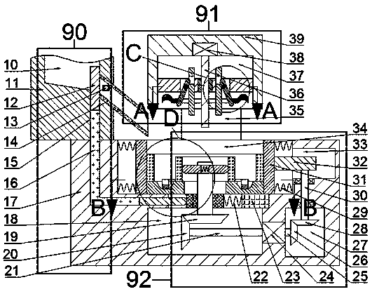
[0023] Combine below Figure 1-6 The present invention will be described in detail. For the convenience of description, the orientations mentioned below are now specified as follows: figure 1 The vertical, horizontal, front and rear directions of the projection relationship are the same.

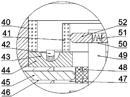
[0024] Attached Figure 1-6 The described ball type ceramic bearing ball equipment includes a lower body 17, a working cavity 34 with an upward opening is provided in the lower body 17, and a positioning plate 44 can be installed on the bottom wall of the working cavity 34. The positioning plate 44 is provided with a positioning hole 43 with an upward opening. The top surface of the positioning plate 44 can be installed with a first holding rack 42 extending into the positioning hole 43. The top surface of the positioning plate 44 can be placed with ceramics. The outer ring 40 and the ceramic inner ring 41 located in the ceramic outer ring 40;

[0025] The bottom wall of the working chamber 34 ...


PUM


Abstract

The invention provides ball mounting equipment for a ball ceramic bearing. The ball mounting equipment comprises a lower machine body, and the bottom wall of working cavity can be provided with locating plates; each locating plate is internally provided with a locating hole with an upward opening, and the top surface of each locating plate can be provided with a first holder extending into the corresponding locating hole; and the top surface of each locating plate can be provided with a ceramic outer ring and a ceramic inner ring located in the ceramic outer ring. According to the equipment, balls are located through the locating holes, and the located balls are fixed after the holders are installed; the distance between the adjacent balls is unchanged, and the balls of the equipment are located accurately; a produced ceramic bearing is high in quality; in addition, a larger space is left in the ball mounting process automatically, and used for packing the balls into the equipment; the balls are not liable to roll out of the rings, and the equipment is safe and reliable, and sensitive in response; the whole mounting process is high in degree of automation, and the equipment is convenient and efficient; and the operation is simple.

Description

Technical field [0001] The invention relates to the field of production and manufacture of transmission components, in particular to a ball type ceramic bearing ball assembly equipment. Background technique [0002] As we all know, as an important mechanical basic part, bearings are often used to support mechanical rotating bodies, reduce the coefficient of friction during its movement and ensure its rotation accuracy. Among the bearings, ceramic bearings have excellent performance that metal bearings cannot match and are widely used. Applications, such as: not afraid of corrosion, low density, light weight, high modulus of elasticity, etc.; but the ceramic material itself is brittle and has low impact resistance. Therefore, the general metal bearing can not directly install the fixed ball in the bearing by pressing. It is suitable for ceramic bearings, but the traditional bearing production line process is cumbersome and the ball installation efficiency is low; the equipment is ...

Claims


Application Information

Patent Timeline
IPC IPC(8): F16C43/06
CPCF16C43/06F16C43/065
Inventor 叶吉利
Owner 浙江国信房地产营销策划有限公司
Why Eureka
Try Eureka