Throttle element for direct-current vapor generator

A technology for steam generators and throttling elements, which is applied in boiler water pipes and promotes water circulation, etc., and can solve the problems of large frictional pressure drop of fluid on the pipe side and failure to provide resistance coefficients, etc.

Pending Publication Date: 2019-09-24
SHANGHAI NUCLEAR ENG RES & DESIGN INST CO LTD
View PDF0 Cites 0 Cited by
  • Summary
  • Abstract
  • Description
  • Claims
  • Application Information

AI Technical Summary

Problems solved by technology

[0003] For larger power once-through steam generators, due to the longer heat transfer tubes, the frictional pressure drop of the fluid on the side of the tubes along the way is relatively large. Requirements to suppress flow instabilities

Method used


Image

  • Throttle element for direct-current vapor generator
  • Throttle element for direct-current vapor generator
  • Throttle element for direct-current vapor generator

Examples


Embodiment

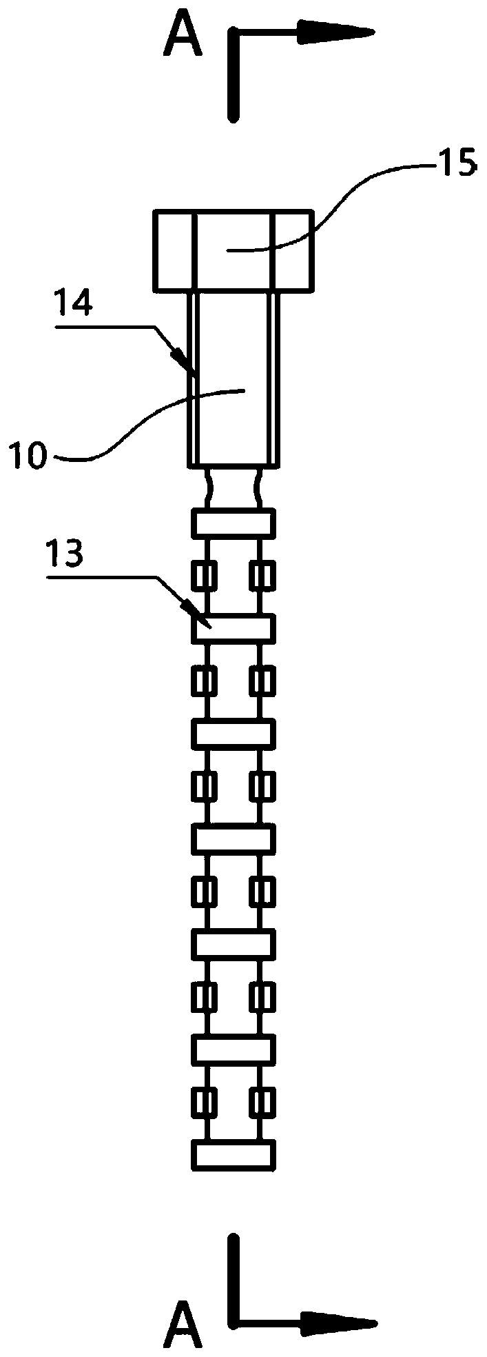
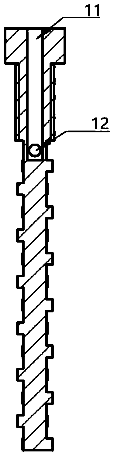
[0019] Such as Figure 1 to Figure 3 As shown, the throttling element for a once-through steam generator of the present invention includes a cylindrical main body 10, an inlet flow channel 11 is arranged at the center of the main body 10, and flow holes 12 are symmetrically arranged on both sides of the bottom of the inlet flow channel 11, and the main body A multistage impeller 13 is arranged on the outside of the lower part of the body 10 , and a sealing thread 14 is arranged on the outside of the upper part of the main body 10 .

[0020] In this embodiment, the main body 10 is installed at the inlet end of the heat transfer tube, and the main body 10 is connected with the inner wall of the heat transfer tube through a sealing thread 14 .

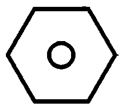
[0021] In this embodiment, the top of the main body 10 is provided with a hexagonal column 15 to facilitate tightening.

[0022] In this embodiment, different numbers of impellers 13 are set according to different resistance coefficient ...


PUM


Abstract

The invention aims at disclosing a throttle element for a direct-current vapor generator. The throttle element comprises a cylindrical body. An inlet runner is arranged in the center of the body. Water flowing holes are symmetrically formed in the two sides of the bottom of the inlet runner. Multiple stages of impellers are arranged on the outer side of the lower portion of the body, and a sealing thread is arranged on the outer side of the upper portion of the body. Compared with the prior art, the throttle element is conveniently mounted at the end of a heat transfer pipe through the sealing thread, the number of the impellers and the size of gaps are selected according to the needed resistance coefficient, the large resistance coefficient can be achieved, no small runner clearance exists, the possibility that blocking happening after long-time operating is reduced, good universality and expansibility are achieved, and the aim of the throttle element is achieved.

Description

technical field [0001] The invention relates to a throttling element structure, in particular to a throttling element for a direct-flow steam generator. Background technique [0002] The operation of the shell-and-tube DC steam generator mainly focuses on two aspects: one is the stability of the overall system operation, and the other is the integrity of the components. The former mainly focuses on the design of feedwater control system and steam pressure control system to provide stable feedwater flow, prevent fluctuations in steam pressure, and stably supply high-quality steam to steam turbines; the latter is mainly related to the structural design of steam generators, such as The structural design of the water supply module and the design of the inlet orifice plate and the throttling part of the heat transfer tube are used to prevent the unstable flow in the tube. [0003] For larger power once-through steam generators, due to the longer heat transfer tubes, the friction...

Claims


Application Information

Patent Timeline
Patent Type & Authority Applications(China)
IPC IPC(8): F22B37/10F22B37/34
CPCF22B37/10F22B37/34
Inventor 巢孟科姚兆祯陈俨林绍萱杨星张菲茜
Owner SHANGHAI NUCLEAR ENG RES & DESIGN INST CO LTD
Why Eureka
Try Eureka